


Designing an Urban Mule E-bike
 11-18-12, 05:22 AM
#1
Transportation Cyclist
Thread Starter

Join Date: Aug 2011
Location: Montana U.S.A.
Posts: 1,206
Bikes: Too many to list, some I built myself including the frame. I "do" ~ Human-Only-Pedal-Powered-Cycles, Human-Electric-Hybrid-Cycles, Human-IC-Hybrid-Cycles, and one Human-IC-Electric-3way-Hybrid-Cycle
Mentioned: 0 Post(s)
Tagged: 0 Thread(s)
Quoted: 22 Post(s)
Likes: 0
Liked 0 Times
in
0 Posts
Designing an Urban Mule E-bike
Okay, so long story short I’ve had “the itch” for a while to build myself an e-bike that fits the following criteria:
1. ----- Fits on a bus bike rack without any issues beyond that of a regular bike
2. ----- Can be loaded down with cargo with cargo racks in both front and rear and can haul a lot of stuff. We are talking Costco runs without a trailer loads usually only possible with a dedicated cargo bike usually with a long wheelbase that won’t fit on a bike bus rack.
3. ----- Has a 60-degree seat to BB angle so that I can easily put a foot down at a stop without having to slip forward off of the seated position for my foot to reach the ground while maintaining an upright riding position to maintain visibility both to see and to be seen.
4. ----- Uses a quiet efficient direct drive brushless hub motor mounted up in the frame driving through the bikes gears like a stoker-monkey set-up. I have a cyclone mid-drive set-up and the noise is annoying but a quite direct drive hub-motor in the wheel doesn’t have the low end tongue for hauling cargo or climbing hills. In frame hub-motor driving through the gears is the only set-up I know of that combines the best of both worlds.
5. ----- Uses a jack-shaft with dual freewheels to combine the motor and pedal input so that the pedals are not driven like an actual stoker-monkey set-up.
6. ----- A standard 7 or 8 speed spool of gears with standard 3/16” width chain with a derailer on the rear. Minimum double possibly triple chain-wheels up front one large one for free running and smaller one(s) for cargo hauling.
7. ----- Rear drop-outs should be forward hooked horizontal drop-outs to accommodate a forward up-angled rear derailer in a protective cage to keep it high and tight to prevent it being damaged or bent inwards in an act of vandalistic sabotage to grab the wheel spokes when shifting into low gear.
8. ----- The additional weight of the battery pack and hub-motor in the frame should be kept as low as possible and as forward as possible for stability both on the road and in a bike rack on a bus.
9. ----- Minimum 36V 20Ah battery capacity with the pack being constructed of high quality modular replaceable LiFePO4 prismatic cells.
10. ----- Sturdy double kick-stand that does not get in the way.
So far after a whole lot of fiddling around in CAD this is what I have come up with so far:
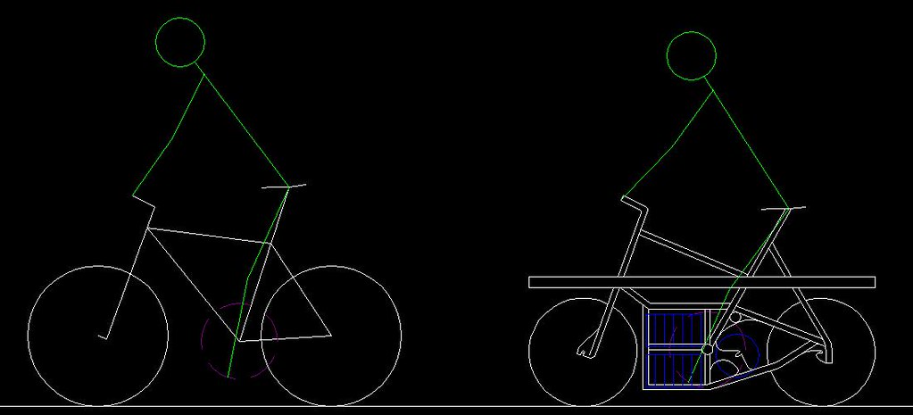
The specifications and geometry of my current “bus bike” and myself are represented in the left side figure. A fairly common 26” wheel bike set-up with a wheel base that is slightly longer then 43 inches and fits on a bus rack just fine but cargo carrying is limited to a rear rack, front & rear panniers, and back-pack where the size of the rear panniers are limited due to heal strike issues and the front panniers cannot be too heavily loaded without severally effecting steering stability. In addition as you can see the represented green stick figure which represents my body proportions cannot put a foot down on the ground at a stop without slipping forward off of the seat.
On the right is what I have come up with so far.
Wheel base is 44” in length with smaller 20” wheels being used. Front fork geometry is more stable for more weight carrying capacity up front without effecting steering a large portion of which can be loaded on the over the wheel front cargo rack formed by a continuous large diameter tube running the full length of the bike and front wheel panniers in most cases will be unnecessary. The same full length large diameter tube that is the spine of the bike forms a generous rear rack as well and large rear panniers or rear basket racks may be attached without heal strike interference issues since the bottom bracket has been moved forward which also provides the ability to easily put a foot down at a stop while remaining seated.
In blue color are the battery pack cells and the hub motor mounted in the frame behind the bottom bracket and forward of the rear wheel. The battery cells represented are high quality third generation LFP-G20 prismatic cells which are 20Ah capacity 3.2V LiFePO4 cells that I can pick up for $31 each plus shipping. They are 2.8” wide which should fit in single file within the frame width, 1.7” thick, and 6” tall not including their screw terminals on the top which should fit as shown in an in-frame double-decker rack forward of the bottom bracket with their weight down low, tight, and forward while still leaving me enough room to mount the motor controller circuit above them but still protected below the main spine beam of the frame.
The gearing jack-shaft would be mounted high above the hub-motor further up the seat-post tube from the bottom bracket so as to accommodate a rear derailer that is tucked up tight and high protected by the right side bottom chain stay which slant downward to connect with the bottom of the battery box built into the frame.
This is basically how the chain lines are worked out with the jack-shaft:
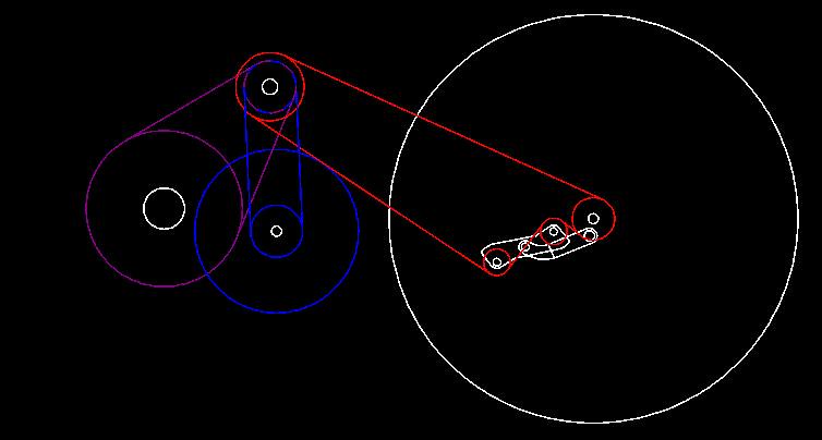
It’s color coded. The light purple colored sprockets and chain lines are from the bottom bracket and pedals up to the jack shaft, a 48 tooth chain wheel turning a 16 tooth single speed freewheel on the right side of the jack shaft. The blue colored sprockets and chain lines are from the frame mounted hub-motor up the jack shaft. A 16 tooth sprocket is attached to the left side of the hub motor represented by the large blue circle via. the six bolt attachment made for a disk brake. This part is available off the shelf as an after market conversion part and is made for people who want a rear flip-wheel on their bikes with one side being a fixy (the sprocket attached to the disk brake mount spot) and a single speed freewheel on the other side for a bike that can be either a single speed or a fixy by just flipping the rear wheel around a process easily accomplished in about 30 seconds with a quick release on the rear. A chain runs up from such a sprocket attacked to the left side of the hub-motor to a left side 16 tooth single speed BMX freewheel on the left side of the jack shaft and thus the jack-shaft can be turned by either the pedals. or the hub-motor, or both. A set of fixed output sprockets are then attacked to the jack-shaft which serve as the main chain-rings for the main chain running back to the rear wheel represented in red with the 7 or 8 speed rear spool and derailer on that rear wheel so that all gears are available to the motor and pedals concurrently. Using a 21 tooth output sprocket on the stub-shaft with 16 tooth input freewheels will increase the gear ratio step-up to 20” rear wheel such that the gear steps are the same as if the bike used the larger 26” wheel size with a 48 tooth front chain-ring. So a 21 tooth would be the large output sprocket on the jack shaft and lower gearing would be accomplished with smaller output sprockets. I would probably put a 15 tooth, an 18 tooth, and a 21 tooth output sprocket on the stub-shaft and rig up a front derailer to move the chain in-between them just like a regular front triple chain ring set-up.
A double kick stand will be mounted to the front of the battery rack part of the frame at the bottom where there is some clearance and will flip forward and up 200+ degrees.
Also, both sides of the center section of the frame that houses the battery pack, hub-motor, motor control electronics, and jack shaft and gearing components to be covered by removable locking sheet metal covers to prevent vandalism or theft of those components. Basically keeping everything nicely boxed up in the frame and covered over on both sides with just the cranks with pedals showing on each side.
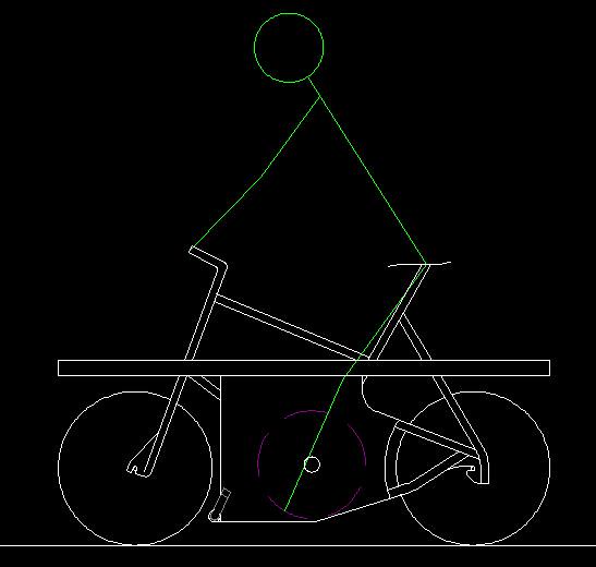
Here is another diagram showing the slabbed over with sheet-metal sides and the kick-stand in place in the folded up position (slightly darker grey color just behind front wheel):
Anyway, thought I would throw out what I’m trying to do and what I’ve got so far on this forum and see if any of you guys could point out anything I might have overlooked or anything like that.
1. ----- Fits on a bus bike rack without any issues beyond that of a regular bike
2. ----- Can be loaded down with cargo with cargo racks in both front and rear and can haul a lot of stuff. We are talking Costco runs without a trailer loads usually only possible with a dedicated cargo bike usually with a long wheelbase that won’t fit on a bike bus rack.
3. ----- Has a 60-degree seat to BB angle so that I can easily put a foot down at a stop without having to slip forward off of the seated position for my foot to reach the ground while maintaining an upright riding position to maintain visibility both to see and to be seen.
4. ----- Uses a quiet efficient direct drive brushless hub motor mounted up in the frame driving through the bikes gears like a stoker-monkey set-up. I have a cyclone mid-drive set-up and the noise is annoying but a quite direct drive hub-motor in the wheel doesn’t have the low end tongue for hauling cargo or climbing hills. In frame hub-motor driving through the gears is the only set-up I know of that combines the best of both worlds.
5. ----- Uses a jack-shaft with dual freewheels to combine the motor and pedal input so that the pedals are not driven like an actual stoker-monkey set-up.
6. ----- A standard 7 or 8 speed spool of gears with standard 3/16” width chain with a derailer on the rear. Minimum double possibly triple chain-wheels up front one large one for free running and smaller one(s) for cargo hauling.
7. ----- Rear drop-outs should be forward hooked horizontal drop-outs to accommodate a forward up-angled rear derailer in a protective cage to keep it high and tight to prevent it being damaged or bent inwards in an act of vandalistic sabotage to grab the wheel spokes when shifting into low gear.
8. ----- The additional weight of the battery pack and hub-motor in the frame should be kept as low as possible and as forward as possible for stability both on the road and in a bike rack on a bus.
9. ----- Minimum 36V 20Ah battery capacity with the pack being constructed of high quality modular replaceable LiFePO4 prismatic cells.
10. ----- Sturdy double kick-stand that does not get in the way.
So far after a whole lot of fiddling around in CAD this is what I have come up with so far:
The specifications and geometry of my current “bus bike” and myself are represented in the left side figure. A fairly common 26” wheel bike set-up with a wheel base that is slightly longer then 43 inches and fits on a bus rack just fine but cargo carrying is limited to a rear rack, front & rear panniers, and back-pack where the size of the rear panniers are limited due to heal strike issues and the front panniers cannot be too heavily loaded without severally effecting steering stability. In addition as you can see the represented green stick figure which represents my body proportions cannot put a foot down on the ground at a stop without slipping forward off of the seat.
On the right is what I have come up with so far.
Wheel base is 44” in length with smaller 20” wheels being used. Front fork geometry is more stable for more weight carrying capacity up front without effecting steering a large portion of which can be loaded on the over the wheel front cargo rack formed by a continuous large diameter tube running the full length of the bike and front wheel panniers in most cases will be unnecessary. The same full length large diameter tube that is the spine of the bike forms a generous rear rack as well and large rear panniers or rear basket racks may be attached without heal strike interference issues since the bottom bracket has been moved forward which also provides the ability to easily put a foot down at a stop while remaining seated.
In blue color are the battery pack cells and the hub motor mounted in the frame behind the bottom bracket and forward of the rear wheel. The battery cells represented are high quality third generation LFP-G20 prismatic cells which are 20Ah capacity 3.2V LiFePO4 cells that I can pick up for $31 each plus shipping. They are 2.8” wide which should fit in single file within the frame width, 1.7” thick, and 6” tall not including their screw terminals on the top which should fit as shown in an in-frame double-decker rack forward of the bottom bracket with their weight down low, tight, and forward while still leaving me enough room to mount the motor controller circuit above them but still protected below the main spine beam of the frame.
The gearing jack-shaft would be mounted high above the hub-motor further up the seat-post tube from the bottom bracket so as to accommodate a rear derailer that is tucked up tight and high protected by the right side bottom chain stay which slant downward to connect with the bottom of the battery box built into the frame.
This is basically how the chain lines are worked out with the jack-shaft:
It’s color coded. The light purple colored sprockets and chain lines are from the bottom bracket and pedals up to the jack shaft, a 48 tooth chain wheel turning a 16 tooth single speed freewheel on the right side of the jack shaft. The blue colored sprockets and chain lines are from the frame mounted hub-motor up the jack shaft. A 16 tooth sprocket is attached to the left side of the hub motor represented by the large blue circle via. the six bolt attachment made for a disk brake. This part is available off the shelf as an after market conversion part and is made for people who want a rear flip-wheel on their bikes with one side being a fixy (the sprocket attached to the disk brake mount spot) and a single speed freewheel on the other side for a bike that can be either a single speed or a fixy by just flipping the rear wheel around a process easily accomplished in about 30 seconds with a quick release on the rear. A chain runs up from such a sprocket attacked to the left side of the hub-motor to a left side 16 tooth single speed BMX freewheel on the left side of the jack shaft and thus the jack-shaft can be turned by either the pedals. or the hub-motor, or both. A set of fixed output sprockets are then attacked to the jack-shaft which serve as the main chain-rings for the main chain running back to the rear wheel represented in red with the 7 or 8 speed rear spool and derailer on that rear wheel so that all gears are available to the motor and pedals concurrently. Using a 21 tooth output sprocket on the stub-shaft with 16 tooth input freewheels will increase the gear ratio step-up to 20” rear wheel such that the gear steps are the same as if the bike used the larger 26” wheel size with a 48 tooth front chain-ring. So a 21 tooth would be the large output sprocket on the jack shaft and lower gearing would be accomplished with smaller output sprockets. I would probably put a 15 tooth, an 18 tooth, and a 21 tooth output sprocket on the stub-shaft and rig up a front derailer to move the chain in-between them just like a regular front triple chain ring set-up.
A double kick stand will be mounted to the front of the battery rack part of the frame at the bottom where there is some clearance and will flip forward and up 200+ degrees.
Also, both sides of the center section of the frame that houses the battery pack, hub-motor, motor control electronics, and jack shaft and gearing components to be covered by removable locking sheet metal covers to prevent vandalism or theft of those components. Basically keeping everything nicely boxed up in the frame and covered over on both sides with just the cranks with pedals showing on each side.
Here is another diagram showing the slabbed over with sheet-metal sides and the kick-stand in place in the folded up position (slightly darker grey color just behind front wheel):
Anyway, thought I would throw out what I’m trying to do and what I’ve got so far on this forum and see if any of you guys could point out anything I might have overlooked or anything like that.
 01-24-13, 08:08 PM
#3
Senior Member
Join Date: Jun 2011
Location: Bend, OR
Posts: 85
Mentioned: 0 Post(s)
Tagged: 0 Thread(s)
Quoted: 0 Post(s)
Likes: 0
Liked 0 Times
in
0 Posts
I like a lot of your ideas. It will be an ambitious project to execute. You mention multiple chainrings but i don't think it will be possible in the space you show and with the chainlines shown. If you have 2 or 3 rings (maybe even just one) i suspect you'll have a hard time overlapping them with the motor, as is shown in the 2nd drawing. Also, in that same drawing, that chainline is very short, so i wonder if you'd have trouble shifting between 2 or 3 rings, even if the motor interference was not a problem?
I'm also designing and hoping to build a 20" cargo/utility e-bike. I have much simpler goals in terms of the electrics. I'm planning a geared hub motor and a "regular" battery of 36v 12-15AH. The geared motor, in a small 20" wheel, will have quite a lot of torque i think. Sufficient for me anyway.
My wife and i each have longtail cargo ebikes right now. They have direct drive hub motors in 26" wheels. The motors are too heavy and have trouble on especially steep hills. The longtails are too big and long. They take up too much space in the garage and can't be put on cars or buses.
I like where you're going! Best of luck!
01-24-13, 08:16 PM
#4
Senior Member
Join Date: Jun 2011
Location: Bend, OR
Posts: 85
Mentioned: 0 Post(s)
Tagged: 0 Thread(s)
Quoted: 0 Post(s)
Likes: 0
Liked 0 Times
in
0 Posts
 01-24-13, 08:35 PM
#5
Senior Member
Join Date: Jun 2011
Location: Bend, OR
Posts: 85
Mentioned: 0 Post(s)
Tagged: 0 Thread(s)
Quoted: 0 Post(s)
Likes: 0
Liked 0 Times
in
0 Posts
If you haven't already see them, you may find inspiration in some of these bikes:
https://james.architectureburger.com/cycle/cargo.html
https://global.rakuten.com/en/search?k=&tl=402012&sm=2
https://www.flickr.com/photos/ultimat...7632038557128/
https://www.bikeforums.net/showthread...els-Cargo-Bike
https://www.adelineadeline.com/bicycl...n/shopper.html
https://www.adelineadeline.com/bicycles/wren/wren.html
https://donkybike.com/gallery/
https://www.kemper-velo.de/bicycles/cargo-bikes/lorri/
https://www.ebscycle.com/
01-26-13, 09:59 PM
#6
Transportation Cyclist
Thread Starter
Join Date: Aug 2011
Location: Montana U.S.A.
Posts: 1,206
Bikes: Too many to list, some I built myself including the frame. I "do" ~ Human-Only-Pedal-Powered-Cycles, Human-Electric-Hybrid-Cycles, Human-IC-Hybrid-Cycles, and one Human-IC-Electric-3way-Hybrid-Cycle
Mentioned: 0 Post(s)
Tagged: 0 Thread(s)
Quoted: 22 Post(s)
Likes: 0
Liked 0 Times
in
0 Posts
@ troysmith80
Yup, I've become aware of the potential issues with jack-shaft in its "as drawn" position in the drawings I posted in the OP of this thread a couple months ago. I'll probably end up having to move the jack-shaft further back and up in the frame which would also tuck the rear derailer arm further up in the frame which would be an added bonus benefit. I may have to do without a front derailer and just have to stop and manually lift the chain and place it on a different sprocket on the jack-shaft since my "proof of concept" experiments for testing how well a standard front derailer can move a chain on the much smaller sprocket sizes has not gone well at all. I do need at least two different chain rings up front on the stub-axle preferably three even if I can only change front chain ring gears by stopping and manually lifting the chain over with my fingers. The gearing range with just a single front chain ring and only rear gears is not wide enough (only 261.5% with a 13-34 rear sprocket spool) to cover my needs. The main hurdle being the difference between "running light" with no or very little cargo load and "fully loaded" with up to a couple hundred extra pounds worth of cargo on board. With only a single front chain ring if I gear for good speed when "running light" at the top end of the gear range the bottom end of the range isn't low enough for running "fully loaded" and if I gear for bottom end pulling power when "fully loaded" at the bottom end of the gear range the top end of the range isn't high enough for decent speed when "running light". With two or three front chain rings with the low end front chain ring being a 16t and the high end being a 21t (just a question of whether there is a third one in-between those two) that opens up my gearing range to 343.3% which is about the same width of gear range as most 10-speed road bikes have. Many mountain bikes and dedicated cargo bicycles (as in two wheels non laterally stabilized) have about a 500% gear range and going with that wide of a range does cover just about everything within human capability from the lowest gear being just barely fast enough to be able to balance the bike to the top end gear being only achievable with proper pedal cadence on the down hill. Some dedicated cargo trikes and quads that don't need to be balanced side-to-side by the rider and thus have no minimum speed have even wider gear ranges some exceeding 1,000% with three or more gear spools with multiple chains. Obviously though, the wider the range the more complexity and I want only as wide of a range as I need in order to try to keep the complexity to a minimum and thus maximize reliability. Having no front derailer and manually moving the chain on the front chain rings according to how much load I'm carrying may be the best option along those lines (think of it like having a road bike with no front derailer to change between the 52t and 40t two front chain rings so you stop at the bottom and top of every big hill to move the chain by hand since the big 52t give you high end gears for the flat and downhill but you need the smaller 40t for climbing big hills to get your gears low enough).
One option that has been suggested to me is to use a 7-8 speed hyper-glide rear freewheel spool on the jack-shaft with the spool reversed (big sprocket on the outside and small sprocket on the inside) as well as on the rear wheel for the rear gears with as short of a chain run as possible putting the jack-shaft just a couple inches away from the rear tire. The individual who suggested that to me claims that with a hyper-glide freewheel spool and a short chain line the front chain will "auto shift" without a derailer because the chain angle from shifting on the rear gears will drag the chain over on the front gears enough for it to catch on the ramps and shift on the front as well. He claims with his set-up (which he has on a delta trike) the middle four or five gears on the front spool get used and are "auto shifted" depending on the chains position on the rear spool. An interesting idea, although I'm somewhat concerned about unexpected auto shifts. I've never ridden a bike that shifts by itself and unexpected shifts could be hard on the knees when pedaling.
Anyway right now I'm still researching my options especially since right now I might have located an efficient high powered brushless-DC motor (thanks to "safe" for the motor equations to calculate how well it would work) that runs on 12V instead of 36V that would be suitable to use instead of the hub motor as a mid-drive so I could potentially build a 12V @ 60Ah power system instead using the same cells just wired in 4s3p configuration instead of 12s1p which would make lighting really easy since I could then use LED automobile tail lights and such to give myself excellent lights at a very reasonable cost that run directly off the main battery. I'm also fine tuning my welding skills with the thin wall stainless steel tubing I want to make the frame out of on this build in preparation for putting the frame together by using it for some other projects I don't necessary have to use stainless for but its good practice since it does take more skill to get a good weld on.
I also am currently using both a long-tail and a home built bakfiets as my cargo bikes and not being able to put them on the bus rack is a big pain in the neck. I don't have the hill climbing problems you have since both of mine are driven through the gears. The long tail has a 360W cyclone 24V set-up on it and the the home built bakfiets has a three way hybrid system that combines a 1.1hp clean burning 4-cycle high efficiency gasoline motor with a 3/4hp. 12V industrial brushed DC motor which is then combined with human pedal power as well all running through the bikes gears and it can comfortably pull its full design weight in cargo (1/4-ton) up any hill I've run across so far except for one gravel hill with about 30% grade I have in my area that it wouldn't climb not because it doesn't have the power but because the drive wheel spins out on the gravel. You should see some of the looks I get from people when I've got a full load on that thing of very obviously heavy items and I'm running it just on pedal and electric power with no motor noise from the IC motor so they think I'm just pedaling only. Both of those bikes though are overkill for a lot of my runs especially the bakfiets which weighs in at over a hundred pounds all by itself not including me and whatever I'm hauling so it is really only good for heavy hauling duty and even if it would fit on a bus rack I really wouldn't want to lift it up into one. With this build I'm trying to keep the weight down to what I can reasonably lift into a bike rack and still have a tough enough frame and strong enough electric drive system to haul a couple hundred pounds of cargo if needed but also be able to run unloaded at in town traffic speed (no less then 20 mph preferably 25+ mph) and have good lights for late trips home at night when the bus isn't running.
One comment I have on your design is that the front cargo rack weight is on the front fork and thus will affect your steering negatively to destabilize it with increasing impact with increased cargo weight. extending the frame forward to form the front rack or attaching the front rack to the frame instead of the fork would be preferred.
01-28-13, 10:02 AM
#7
Senior Member
Join Date: Jun 2011
Location: Bend, OR
Posts: 85
Mentioned: 0 Post(s)
Tagged: 0 Thread(s)
Quoted: 0 Post(s)
Likes: 0
Liked 0 Times
in
0 Posts
My bike will have the front rack frame-mounted, not fork, BikeCad just doesn't allow you to design it that way, so i'm using what BikeCad allows, for the sake of visualization. Maybe I should just photoshop that image, because that's the same thing everyone says :-)
Have you considered using an internally geared hub on the jackshaft? Then you could use a single chainring on the cranks, and have your gearing acheived through the jackshaft gear set and the rear wheel gearing.
Depending on your budget, there are a lot of other possibilities. One is an internally geared crankset:
https://pattersonbike.com/
https://www.joe-bike.com/2012/03/11/r...peed-crankset/
https://www.cyclemonkey.com/schlumpf-innovations.shtml
There's another one that i can't seem to find right now but it's a high-quality unit, German made i think, with at least 2 speeds in the crank.
Another would be a Rohloff rear hub with 526% gear range without any other gearing required. https://sheldonbrown.com/harris/rohloff.html
02-11-13, 10:34 AM
#8
Transportation Cyclist
Thread Starter
Join Date: Aug 2011
Location: Montana U.S.A.
Posts: 1,206
Bikes: Too many to list, some I built myself including the frame. I "do" ~ Human-Only-Pedal-Powered-Cycles, Human-Electric-Hybrid-Cycles, Human-IC-Hybrid-Cycles, and one Human-IC-Electric-3way-Hybrid-Cycle
Mentioned: 0 Post(s)
Tagged: 0 Thread(s)
Quoted: 22 Post(s)
Likes: 0
Liked 0 Times
in
0 Posts
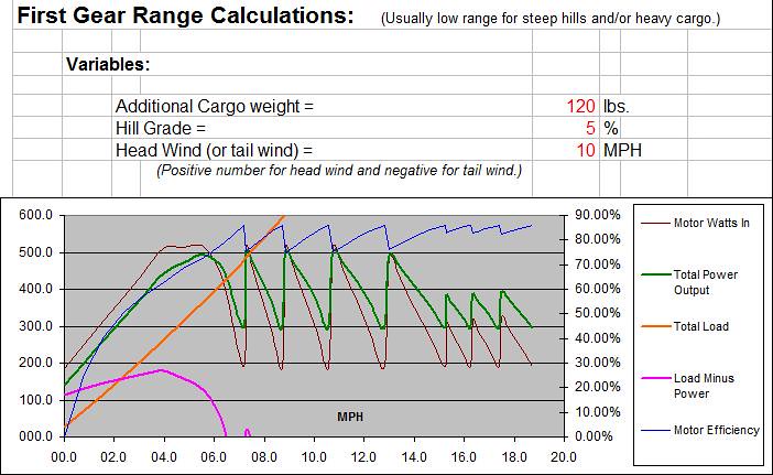
Well, with some pointers in the right direction from fellow forum member "safe" I managed to put together a monstrosity of an MS-Excel spreadsheet to calculate performance figures with a variety of motor and gearing configurations for this potential build project. I think I found a combination I like for a low voltage set-up using a 6354 RC motor running on a 4s3p pack of 20Ah LiFePO4 prismatic cells. 52t chain ring on the crank turning a 16t freewheel on the jack-shaft which is also turned by the motor via. a #25 chain with a 10t sprocket on the motor and an 80t sprocket on the jack-shaft. And then three output sprockets on the jackshaft, a 14t, 18t, and 22t which the chain is manually switched between and runs back to a 34,28,23,19,16,15,14,13 spool on a rear 20" wheel.
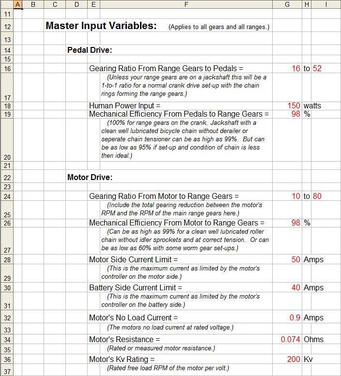
Simulation with the chain on the smallest 14t drive sprocket on the jackshaft pulling a 5% hill climb with a 10mph head-wind while hauling an additional 120lbs. of cargo. Just barely enough power to shift into second gear and hold about 7.7mph under those conditions while using no more then 500watts from the battery.
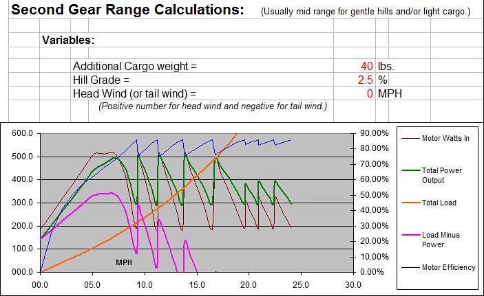
Simulation with the chain on the middle 18t drive sprocket on the jackshaft pulling a 2.5% hill climb with no head-wind while hauling an additional 40lbs. of cargo. Just barely enough power to shift into fifth gear and hold about 16.5mph under those conditions while using no more then 500watts from the battery or I can holding low in Fourth gear at a fast 90 RPM pedal cadence and only draw about 365watts from the battery at a just slightly lower speed of 15mph.
Simulation with the chain on the high 22t drive sprocket on the jackshaft on the flat with no head-wind and no additional cargo weight. Plenty enough power to hold fifth gear and press into it and bring my pedaling cadence up for a respectable cruising speed of about 22mph while only pulling 350watts from the battery while its in the upper end of its efficiency range and it only takes the slightest down slope of a mere percentage point or a light tail wind of only a few miles per hour to allow me to push up into the higher gears and pull my speed up over the 25mph mark.
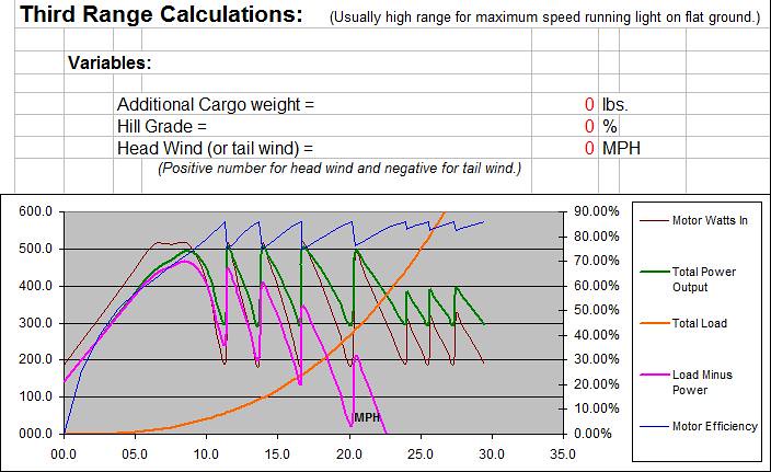
Looks pretty good to me at least on paper. Need to ask safe a couple more questions to finish off my spread sheet and figure out how to figure range at reduced throttle settings. Right now I can only calculate range at the points where the motor peaks out and its output power drops to match the load as its RPM's start to top out.
Simulation with the chain on the smallest 14t drive sprocket on the jackshaft pulling a 5% hill climb with a 10mph head-wind while hauling an additional 120lbs. of cargo. Just barely enough power to shift into second gear and hold about 7.7mph under those conditions while using no more then 500watts from the battery.
Simulation with the chain on the middle 18t drive sprocket on the jackshaft pulling a 2.5% hill climb with no head-wind while hauling an additional 40lbs. of cargo. Just barely enough power to shift into fifth gear and hold about 16.5mph under those conditions while using no more then 500watts from the battery or I can holding low in Fourth gear at a fast 90 RPM pedal cadence and only draw about 365watts from the battery at a just slightly lower speed of 15mph.
Simulation with the chain on the high 22t drive sprocket on the jackshaft on the flat with no head-wind and no additional cargo weight. Plenty enough power to hold fifth gear and press into it and bring my pedaling cadence up for a respectable cruising speed of about 22mph while only pulling 350watts from the battery while its in the upper end of its efficiency range and it only takes the slightest down slope of a mere percentage point or a light tail wind of only a few miles per hour to allow me to push up into the higher gears and pull my speed up over the 25mph mark.
Looks pretty good to me at least on paper. Need to ask safe a couple more questions to finish off my spread sheet and figure out how to figure range at reduced throttle settings. Right now I can only calculate range at the points where the motor peaks out and its output power drops to match the load as its RPM's start to top out.
02-18-13, 01:47 AM
#9
Transportation Cyclist
Thread Starter
Join Date: Aug 2011
Location: Montana U.S.A.
Posts: 1,206
Bikes: Too many to list, some I built myself including the frame. I "do" ~ Human-Only-Pedal-Powered-Cycles, Human-Electric-Hybrid-Cycles, Human-IC-Hybrid-Cycles, and one Human-IC-Electric-3way-Hybrid-Cycle
Mentioned: 0 Post(s)
Tagged: 0 Thread(s)
Quoted: 22 Post(s)
Likes: 0
Liked 0 Times
in
0 Posts
Okay, got the range calculations figured out, when in doubt I tilted them towards more juice being pulled by the motor and less range rather then more so they are tilted towards the conservative side of the spectrum.
At this point I'm pretty set with using a Twin pair of 6354 RC motors the heavier duty ones with 10mm instead of 8mm center shaft and heavier copper wires then standard. I can pick them up for less then $100 each shipped to my door. If I install a longer shaft in them to suspend them in the frame between an extra set of heavy duty bearings to take the load off the stock bearings in the motor which aren't designed to handle heavy side thrust loads. Two separate twin motors running off of their own twin controllers on separate circuits off of a single throttle. So I can run the bike using either motor or both, longer range and slower speed on only one motor or higher speed with a shorter range and better climbing and hauling capabilities, not to mention the inherent greater reliability with the redundancy of having two drive systems. Here is what I'm showing for the potential capabilities with that kind of set-up, same conditions as in the previous posts above for the same gear ranges:
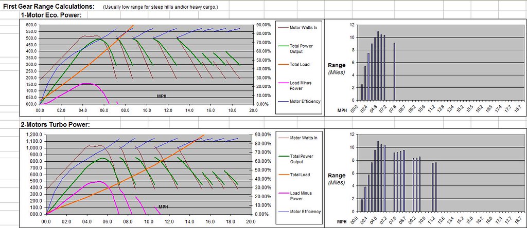
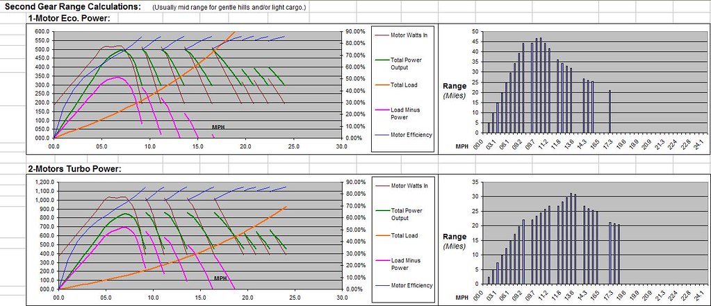

And this is what it looks like under human power only for the same conditions. The hard spike at the beginning of the graph is the initial acceleration when standing up on the pedals and "mashing it" and after that its sit down strong and steady pedaling:

At this point I'm pretty set with using a Twin pair of 6354 RC motors the heavier duty ones with 10mm instead of 8mm center shaft and heavier copper wires then standard. I can pick them up for less then $100 each shipped to my door. If I install a longer shaft in them to suspend them in the frame between an extra set of heavy duty bearings to take the load off the stock bearings in the motor which aren't designed to handle heavy side thrust loads. Two separate twin motors running off of their own twin controllers on separate circuits off of a single throttle. So I can run the bike using either motor or both, longer range and slower speed on only one motor or higher speed with a shorter range and better climbing and hauling capabilities, not to mention the inherent greater reliability with the redundancy of having two drive systems. Here is what I'm showing for the potential capabilities with that kind of set-up, same conditions as in the previous posts above for the same gear ranges:
And this is what it looks like under human power only for the same conditions. The hard spike at the beginning of the graph is the initial acceleration when standing up on the pedals and "mashing it" and after that its sit down strong and steady pedaling:
02-18-13, 12:08 PM
#10
Senior Member
Join Date: Feb 2009
Posts: 160
Mentioned: 1 Post(s)
Tagged: 0 Thread(s)
Quoted: 0 Post(s)
Likes: 0
Liked 1 Time
in
1 Post
Don't forget about cogging...
https://en.m.wikipedia.org/wiki/Cogging_torque
If you use two motors and hope to have the option of running just one sometimes you better be sure that the non-running motor is not physically connected because having to overcome cogging torque is a big drag on power.
Cogging is when the iron core reacts to the movement of the magnets unaided by electrically induced fields.
Not only that... but if the spare motor remains connected it will attempt to act as a generator.
Better to use just one motor.
https://www.hobbyking.com/hobbyking/s...arehouse_.html

...no load @ 1.65 amps is excellent.
.
https://en.m.wikipedia.org/wiki/Cogging_torque
If you use two motors and hope to have the option of running just one sometimes you better be sure that the non-running motor is not physically connected because having to overcome cogging torque is a big drag on power.
Cogging is when the iron core reacts to the movement of the magnets unaided by electrically induced fields.
Not only that... but if the spare motor remains connected it will attempt to act as a generator.
Better to use just one motor.
https://www.hobbyking.com/hobbyking/s...arehouse_.html
...no load @ 1.65 amps is excellent.
.
Last edited by safe; 02-18-13 at 12:16 PM.
02-18-13, 07:58 PM
#11
Transportation Cyclist
Thread Starter
Join Date: Aug 2011
Location: Montana U.S.A.
Posts: 1,206
Bikes: Too many to list, some I built myself including the frame. I "do" ~ Human-Only-Pedal-Powered-Cycles, Human-Electric-Hybrid-Cycles, Human-IC-Hybrid-Cycles, and one Human-IC-Electric-3way-Hybrid-Cycle
Mentioned: 0 Post(s)
Tagged: 0 Thread(s)
Quoted: 22 Post(s)
Likes: 0
Liked 0 Times
in
0 Posts
I intend to attach the two motors to the main jack-shaft via. two separate #25 chains with separate freewheels on the separate chain sprockets. The only additional drag when only one motor is running will be what is in the freewheeling mechanism which isn't much for a well lubricated single speed bicycle type freewheel or even less for a sprag clutch one way roller bearing freewheel unit. This is the best price I've found anywhere for an 80+ tooth count sprocket in #25 chains size:
https://www.staton-inc.com/store/prod...es-1752-0.html
And I can either use it as designed with a 16t single speed freewheel inside it using four mounting bolts or I can re-drill for a 2.63" five hole chain ring bolt pattern and use any of these options for the freewheeling mechanism:
https://www.staton-inc.com/store/prod...ch-967-35.html
https://www.staton-inc.com/store/prod...el-1329-0.html
https://www.sickbikeparts.com/catalog...5dng6mouhqc715
Long story short two separate chains with separate freewheels from the jackshaft to each each motor will cost me a little bit in weight and about 2% in efficiency (thankfully roller chain has a very high mechanical efficiency). A single bigger motor would be nice in some ways but not in others, the extra redundancy is a really nice plus with the two drive systems only sharing a single throttle and battery pack so only a problem with either the battery or the throttle assembly could take the whole thing down, and if I use twin Kelly controllers running of a single Hall throttle, the throttle can be "jury rigged" in a pinch to a simple on/off switch (preferably a dead man type switch spring loaded to the off position) with only one controller turned on (and thus only one motor drive running so its at the lower power level) and in that configuration it would still be fully drive-able so in that case the battery is the only terminal failure point and even then there is redundancy since it is made up of three parallel sections of four series cells so as long as at least one of those three parallel sections is still good the others could be disconnected with their screw top terminals.
Yes, it means I'll be doubling up on a lot of the components and thus the cost but two of each of lower cost but still quality components vs. one each of bigger higher cost components is going to end up pretty close.
In addition I'm trying to keep the width of the power core that is housed in the center of the bike less then 5" wide and preferably as close to the 3" wide mark as possible with only the occasional protrusion of a set of bearing housings with the ends of the motor axles or stub-shaft axle in it further out. You get into motors much bigger then a 6354 and they start making them longer as well as bigger around. 54mm is a nice width to be able to add a sprocket, cooling fan and an extra set of bearings and still get it to be nice and narrow. I intend to offset the sprockets and the cooling fans to offset to two motor drive chains on the left side of the bike. Motors to the right side with the back mounts with the wires coming out bolted up to the right cover panel with outer magnent shell bell to the left and then the cooling fan then the 10t #25 chain sprocket then the left cover panel on the primary motor and then reverse that order with the sprocket next to the motor and the cooling fan outboard against the left cover panel for the other motor so the two chain lines are offset slightly on the far left side running up to the two 80t #25 sprockets each with their own freewheel units on the left side of the jack-shaft with the right side of the jacks-haft left open for the pedal power input chain coming up from the crank to its freewheel and then the solidly fixed output sprockets on the far right outside end of the jackshaft for the combined power output back to the rear drive wheel gear spool. I'll draw an updated chain diagram later in CAD and add it to this thread.
Basically I know the type of frame I want to build so I intend to build the drive system contained within two aluminum side plates complete with the jack-shaft first in a general shape and width I know will work with the kind of bike frame I want to build and then when I've got that done then get out the stainless square tube and round tube and the welder and build the main frame top bar and main frame triangle and low and forward battery box around that on a simple flat table jig then jig it up really straight and true triple checking everything for welding the rear drop outs and head tube along with the crank tube all straight and true to the frame built on a simple flat jig and then move on from there.
Since I'm doing my own frame to fit my needs I think it best to build the power core first being sure it will work with the kind of frame I want to use and then build the frame around it rather then build the frame first and then try to get the power core to fit in the frame.
02-18-13, 08:12 PM
#12
Senior Member
Join Date: Feb 2009
Posts: 160
Mentioned: 1 Post(s)
Tagged: 0 Thread(s)
Quoted: 0 Post(s)
Likes: 0
Liked 1 Time
in
1 Post

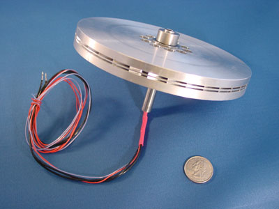
What we all need is a high powered and high efficiency pancake (thin) motor.
One of these days someone will build one perfect for our needs. (that's cheap)
Motor selection is "still" a matter of compromises...
I ended up with a brushed motor simply because everything else was expensive or fragile.
Two motors might be more narrow, but it doubles your work.
...and it took 5-6 years to build mine, so it's easy to underestimate the effort on these projects.
.
Last edited by safe; 02-18-13 at 08:50 PM.
02-19-13, 01:04 AM
#13
Transportation Cyclist
Thread Starter
Join Date: Aug 2011
Location: Montana U.S.A.
Posts: 1,206
Bikes: Too many to list, some I built myself including the frame. I "do" ~ Human-Only-Pedal-Powered-Cycles, Human-Electric-Hybrid-Cycles, Human-IC-Hybrid-Cycles, and one Human-IC-Electric-3way-Hybrid-Cycle
Mentioned: 0 Post(s)
Tagged: 0 Thread(s)
Quoted: 22 Post(s)
Likes: 0
Liked 0 Times
in
0 Posts
Doubles the work with two nearly identical installs. If you had to build a second bike nearly the same as yours assuming you had the funds and didn't have to wait for the money to build up taking part of each pay or retirement or other income check do you think you could be faster on the second build that was nearly the same?
What I'm saying is semi-customized production line mentality. Install, and hook up one motor and controller and the steps to do the second is nearly identical so it should go easier on the second. Provided you keep things close to the same repeat operations become easier and quicker. Every build I have done so far in terms of complexity and grunt work per hour has gone faster except for the parts that I had "never done that before". At this point I could probably do a simple hub-motor, decent electric mid-drive kit, or Staton-Inc weed-whacker motor kit build on a suitable bike in a weekend. Granted far more complex builds take much longer especially when you get into frame modification especially extensive frame modification, or even more so with building completely from scratch and total fabrication from the ground up.
My last build which I just completed this fall was a complicated build but wasn't completely from scratch from the ground up. About a year of non-dedicated but, “I’m going to build something like this sooner or later so start thinking about it and gathering ideas” sort of planning; followed by 2-3 months of dedicated planning and component sourcing and then 4-6 months build time and work out the bugs or so. Hard to say exactly since I don’t work on it consistently but pick away at it with a day here and an evening there. It’s a heavy cargo bakfiets front load low-boy flatbed cargo hauler. An old heavy duty steel mountain bike frame, modified and strengthened with the drop outs reinforced heavily and opened up to accept a 14mm heavy axle was used to build the tail end. Big strong SS square tube forms the main strength beam forward with the low-boy flatbed cargo built on top of it and then used an old steel BMX kids bike front end to build the front wheel. 48-spoke Yuba heavy cargo 26" wheel in the rear and a 64 spoke crazy strong 20" BMX trick bike front wheel up front modified to accept a front 203mm disk brake (same on rear). Chopped out the bottom bracket on the old mountain bike frame and put in a nice big round SS tube instead with two on each side pressed in big ball bearing races stuffed with Staton-Inc super-duty freewheeling bottom bracket parts and then used one of his big double stage gear boxes with a 1.1hp 25cc 4-cycle Robin-Subaru motors on the 7,000-RPM input point and then took a 3/4hp Industrial brushed 12V motor (one of those big heavy 40-lbs. ones that have an output in the 1,800-RPM range with a big diameter keyed shaft and hooked it up to the middle point on the gear box that is in-between the two gear reduction stages using two twin chains with one chain being a freewheel attachment to allow the gas engine to drive while the electric motor is dormant and not turn the electric motor (since the gas engine has a centrifugal clutch running the electric motor with the gas engine dormant is already taken care of) and then put a 12V electric clutch on the second chain drive so that when the clutch is engaged there is no longer freewheeling between the electric motor and the gear box so the gas engine will drive the electric motor as a generator to charge the battery. And finally I used a BMX type heavy duty freewheel on the output from the gear box running a chain up to the freewheeling crank assembly getting another gearing reduction step in the process. Gas motor is simple pull start and twist throttle. Electric motor set-up is controlled by primarily by a heavy duty three way on/off/on toggle switch with one end of the switch engaging the electric clutch and diode assembly to use the motor as a generator to charge the batteries off of the power of the gas motor and the other end hooked up to a simple momentary push button switch that needs to be held down to engage the electric motor, simple on/off throttle action for the electric motor.
I haven’t taken any pictures of it and I don’t intend to or to post them online because it is UGLY especially since I hate to mess with paint and all the prep work that goes with it (which is why I use SS tubing instead of regular steal tube) and the old bike parts are their original color and the stainless is shiny except for around the welds which are dark (I used non-rust rod good for welding SS-to-SS or SS-to-mS or SS-to-CM but the welds aren’t shiny when you use a cross metal rod instead of a dedicated SS-to-SS only rod.) and it doesn’t have “nice lines” and even if all painted up nice and all the drive system cowled in it would still look kind of ugly.
She wasn’t designed to be a beauty queen or a speed queen but rather a tough strong and steady but slow work horse. Something I can haul up to a quarter ton of cargo with (frame can handle more then that but that is what the wheels can take) including small loads of rock and gravel and other building materials and feed for the stock and all that sort of stuff. Basically a crossbreed between a bicycle and a wheel-barrow with both an electric and a gas motor on it along with human powered pedal drive that has low enough gears to climb almost any hill unloaded and most road grades even fully loaded, can sustain long distance travel getting over a hundred miles per gallon of gas, but can also run silent on the electric motor in-town or on bike baths were electric assist is okay but gas power is not and I can also engage the electric motor to give an extra power boost to the gas motor when needed running both at the same time for holding decent speed while climbing a hill and then switch to generator mode on the down hill side or even on the flat if your willing to slow down due to not having as much power available to drive the vehicle.
I think you get the basic idea of that build.
I won’t deny for a second that this one is going to take a lot more time, but I think I can get it done within a reasonable time period. This one needs to look presentable and weight is a concern since I need to be able to lift it into a bike rack on a bus and also not have it too heavy so as to put too much weight on their racks. I can tell you I’m doing a lot more planning work on this one. So far the only thing I’ve actually put together and done some welding and fabrication on was only a test rig to see if a standard front derailer could move the chain on much smaller then normal front drive sprockets since I intend to use output sprocket sizes on the jack-shaft that are more in line of what is commonly used on rear wheel gear spools (and may even use a rear gear spool itself with the freewheel guts torn out and welded solid on an adapter to fit a standard keyed shaft drive) and that told me what I need to know. Namely, that it works with the smaller size sprocket but not very well and I’d just be better off stopping and manually moving the chain to whichever front drive sprocket I need for conditions and just using the rear gears within that range for shifting on the fly.
And, oh, yes I agree on the thin disk motors, to a point. From the reading I’ve done over on the endless-sphere forum (gets a little over my head sometimes with those guys) the physical shape of a motor and its performance are not completely unrelated. Small diameter but long length motors aren’t top end performers and neither are thin but large diameter motors. A lot of complaining over there about direct drive hub motors being too thin and large diameter for best performance and efficiency and they weigh too much because of their shape. Some of the best performing motors that they are using over there on some of their top end builds with 90+% efficiency at multiple Kw of power and going way fast (faster then I would feel safer going on a light weight bike that had components especially front fork and wheel components only designed for pedal speeds) are smaller diameter and wider specially designed hub-motors that require wider rear drop outs then normal in the 150-200mm range.
So unfortunately, it sounds like if we want to stay in the top end of the efficiency range with minimal weight we are pretty much stuck with “round brick” shaped motors and having to find motors that are “close enough” for our needs and then retro-fitting them to work. On my big ugly heavy hauler build the best option was using a big heavy industrial brushed motor. That would be all wrong for this build and it certainly wasn’t ideal for that build but it was the best choice readily available to me at a reasonable price.
02-19-13, 09:41 AM
#14
Senior Member
Join Date: Feb 2009
Posts: 160
Mentioned: 1 Post(s)
Tagged: 0 Thread(s)
Quoted: 0 Post(s)
Likes: 0
Liked 1 Time
in
1 Post
About motors...
It's really a question of "axial" vs "radial" design. Most all RC motors are radial outrunners, which means the magnetic lines of force go in a radial direction (from in to out and back) and the part that spins is on the outside.
Axial motors have magnetic lines of force that go side to side out at the end of a thin disc.

Using Halbach Arrays adds an extra level of magnetic force.
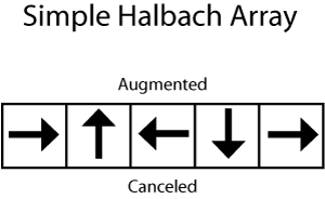
One "big feature" of an axial motor using Halbach arrays other than high efficiency is NO COGGING.
This means if ever in the future we can get someone building these for ebikes we can directly attach the motor without a freewheel because the drag with these motors is so small.
Radial motors squished thin don't do as well because they waste too much copper rounding corners and not adding to magnetic force. (that's why)
About timelines...
You used terms like "years" to complete things and that says to me you have a realistic idea of the time involved with these projects.
My project actually did "run" a few years ago with a completely different drivetrain, but it was no where near reliable enough to use. And at that time I was using NiCads not LifePo4.
.
It's really a question of "axial" vs "radial" design. Most all RC motors are radial outrunners, which means the magnetic lines of force go in a radial direction (from in to out and back) and the part that spins is on the outside.
Axial motors have magnetic lines of force that go side to side out at the end of a thin disc.
Using Halbach Arrays adds an extra level of magnetic force.
One "big feature" of an axial motor using Halbach arrays other than high efficiency is NO COGGING.
This means if ever in the future we can get someone building these for ebikes we can directly attach the motor without a freewheel because the drag with these motors is so small.
Radial motors squished thin don't do as well because they waste too much copper rounding corners and not adding to magnetic force. (that's why)
About timelines...
You used terms like "years" to complete things and that says to me you have a realistic idea of the time involved with these projects.
My project actually did "run" a few years ago with a completely different drivetrain, but it was no where near reliable enough to use. And at that time I was using NiCads not LifePo4.
.
Last edited by safe; 02-19-13 at 10:08 AM.
02-20-13, 10:57 AM
#15
Senior Member
Join Date: Feb 2009
Posts: 160
Mentioned: 1 Post(s)
Tagged: 0 Thread(s)
Quoted: 0 Post(s)
Likes: 0
Liked 1 Time
in
1 Post
While we are talking about "perfect world" scenarios for motors...
Motor rpm is determined by internal pole count.
My brushed motor has only four magnets and therefore two pole pairs.
Most RC motors have 14 magnets and seven pole pairs.
As you increase pole pairs it reduces the motor rpm because it takes more electrical cycles to get one physical cycle out of the motor.
One could imagine a motor with 40 magnets and 20 pole pairs that was done as an axial motor with Halbach Arrays and carbon fiber. (like above) If you placed such a motor on the bike as a "chainring replacement" then you could eliminate all the "motor-to-bike" adaptation issues.
The problem has always been that we are using generic or other purposed motors and never designed for the unique needs of an ebike.
.
Last edited by safe; 02-20-13 at 11:07 AM.
02-20-13, 11:59 AM
#16
Certified Bike Brat
Join Date: Jan 2011
Location: Montreal, Quebec
Posts: 4,251
Mentioned: 0 Post(s)
Tagged: 0 Thread(s)
Quoted: 5 Post(s)
Likes: 0
Liked 6 Times
in
6 Posts
How about restrictions?
Thigs may be different where you are but thats the state of things in major cities in Canada. The racks simply aren't built to handle anything except light recreational bicycles.
Motorized bicycles, electric-poweredbicycles and bicycles equipped withchild carriers are not allowed on the busbike racks.
Last edited by Burton; 02-20-13 at 12:03 PM.
02-20-13, 07:54 PM
#17
Transportation Cyclist
Thread Starter
Join Date: Aug 2011
Location: Montana U.S.A.
Posts: 1,206
Bikes: Too many to list, some I built myself including the frame. I "do" ~ Human-Only-Pedal-Powered-Cycles, Human-Electric-Hybrid-Cycles, Human-IC-Hybrid-Cycles, and one Human-IC-Electric-3way-Hybrid-Cycle
Mentioned: 0 Post(s)
Tagged: 0 Thread(s)
Quoted: 22 Post(s)
Likes: 0
Liked 0 Times
in
0 Posts
@ Burton
I agree that in some areas that could be an issue. It is not with the local bus services I have dealt with, however, at least not so far. This build should be considerably lighter weight (no cargo) then one of my current e-bikes I have already put in the bus racks many times that has a big monster 1.4 Kw Brute motor in the rear wheel and a heavy NiMH pack that fills the entire frame triangle. One of these days that bike is going to get upgraded to a LiFePO4 pack and I should see a considerable weight savings in doing so but I'm not spending the money for that until the current pack starts to degrade enough that it needs replaced. I've also put a bike equipped with a Staton-Inc axle mount chain drive kit in the bike rack on the bus several times as well. All but one of the busses that run locally have big strong metal bike racks on front. The one odd bus out has a rack that has as strong or stronger metal center beam but unfortunately the slots for the bike tires are some kind of rubberized plastic. No one really likes that rack, bus drivers, or us guys that put our bikes into it and the only one of my bikes with a motor I will put into that rack is my bike with the hill helper motor that only has only about 12-lbs extra weight for the hill helper assist unit total added weight for all its components and the custom rack it is built into and is a "stealth" set-up that is built inside the right side rear pannier with a second chain going down to the big 34t granny gear on the rear sprocket spool. That bike even with its hill helper motor assist is lighter weight then a lot of steel frame cruiser type bikes out there and I could probably sneak that onto just about any bus including those busses up in Canada that specifically forbid e-bikes unless someone looked really closely and noticed the second chain coming out the bottom of the right side rear pannier and realized there was a motor, controller, and battery on a solid frame built inside that pannier bag.
I have seen one of the bus drivers ask one biker to bring in some of his cargo in his pannier bags into the bus to reduce the weight on the bike rack. The guy had a pedal only bike that must have been loaded down with a hundred pounds of cargo or so in four giant pannier bags, two in front and two in the rear, and he had to lift the front and rear of the bike into the bike rack separately and struggled to do so even then and watching him struggling to lift it into the rack is what prompted the driver to ask him to do this (along with two other bikes already being in the rack so it was full up, as well, I'm sure.).
Long story short, at least locally, so long as I keep the weight down to a reasonable level and I can walk up and lift the bike into the rack on the bus without having difficulty doing so I shouldn't have a problem and I'm pretty sure this build is going to end up lighter than the 1.4 Kw Brute hub-motor bike I already put in the bus rack and about the same but with better more centered and lower weight distribution then the Staton-Inc internal combustion axle mount kit bike I’ve put into the bus racks too. Granted it’s not going to be as light and as stealthy as my hill helper only motor build but I don't seem to have a problem locally and even if I did I would still want a short wheel base motor assisted cargo bike along these lines. Wouldn't be quite as big of priority but would still want enough to accept the time and cost of a build like this, just might not be quite as motivated.
I should note that most if not all of the bus trips would be one way with little to no cargo and then coming back under my own power with a full cargo load (pick up stuff on the way into work and have my bike loaded and ready to go sitting in the work shop) late at night when I get off work when the bus isn't running. Which is why doing a low voltage 12V build is so attractive to me because then I can use big bright and low cost commercial tractor-trailer LED tail and marker lights, and rig up a LED headlight system using 12VDC LED track light bulbs on it running directly off the main pack without having to use a DC/DC voltage converter to light me up at night better than a motor cycle and far beyond what all but the most expensive and powerful bicycle lights are capable of at a very reasonable price point.
@ safe
Now that I understand what you are talking about with a disk motor I most certainly agree that they look like they would be ideal for our needs. And I agree that if they are capable of being set-up to run at low enough Kv levels that building them right into the bikes crank inside of the chain rings would be an ideal set-up. You would probably need to set-up the bike with a narrow bottom bracket that was off center to the left side to give more room on the right side to allow for a standard pedal width on the crank and not have an expanded G factor on the crank and accommodate the motors width but that wouldn't be difficult to work out. Another idea I've often had concerning hub-motors (sounds like a disk motor would make a better hub-motor then how they build them now) would be considering that they currently build hub-motors that are not direct drive and have an internal planetary gear reduction between the motors out-runner magnet shell and the actual wheel, with a little bit of ingenuity it seems to me it should be possible to build a hub-motor where the center of the hub-motor was an Internal Gear Hub and the motors power ran through the internal gears along with the human input from the drive chain sprocket so that when you changed gears up or down it also geared the motor up or down within the hub as well. Granted IGH can only take so much torque and those who have built mid and crank drive bikes running the power of the motor and pedals together through a rear internal gear hub have found that only the tougher 3 speed and a few of the 5 speed hubs can take the extra power and hubs with more internal gears then that can’t take the extra stress beyond a very low power build that doesn’t stress the internal hub gears any more than human pedal power does because with higher gear counts the internal planetary gear sets are smaller and lighter duty in order to get more of them inside the hub to provide more gears. But even only three gears at a standard 3:4, 1:1, 4:3 ratio steps would provide a considerable improvement in the performance, especially efficient hill climbing ability, compared to a direct drive or single gear ratio hub-motor. So I could certainly see a rear hub motor built using one of these disk type motors that in the center of the motor disk had a 3-speed IGH instead of a standard hub with the power of the motor running through those gears so you would have lower gears for efficient hill climbing as well as top end speed out of a hub-motor in the top gear ratio.
Last edited by turbo1889; 02-20-13 at 07:58 PM.
02-21-13, 10:21 AM
#18
Senior Member
Join Date: Feb 2009
Posts: 160
Mentioned: 1 Post(s)
Tagged: 0 Thread(s)
Quoted: 0 Post(s)
Likes: 0
Liked 1 Time
in
1 Post


https://www.imtmotors.com/technology.htm
Technology
The IMT motor is a single sided axial flux permanent magnet (PM) brushless motor with a slotted iron stator.
Axial flux motors are disc shaped, rather than the more commonly available drum shape that is typical of radial flux motors.
The disc shape is the result of the stator and rotor being placed adjacent to each other rather than the rotor spinning inside the stator cylinder.
Axial flux motors are usually described by industry as axial air gap or "pancake" motors.
Increased availability and reduced cost of both power electronics and magnetically strong materials (such as neodymium iron boron) has enabled the development of the IMT motor design.
The combination of these technical advances allows dramatic improvements in efficiency (particularly of small machines) and/or variable speed drives that remove the need for geared transmissions in some applications.
-------------
Hub motors are extremely heavy as well as inefficient. The switch to an external motor connected through a chain and sprockets actually is an improvement. The axial flux application to the hub fits somewhere between the two in performance.
This particular axial motor is just one sided... so it's only half of the potential. Likely the stator is fixed and a single set of magnets spin with the wheel. This is less than ideal.
Applying the axial flux concept to the bottom bracket would be innovative. I'm not sure if anyone has done it yet.
They have multispeed bottom brackets now:
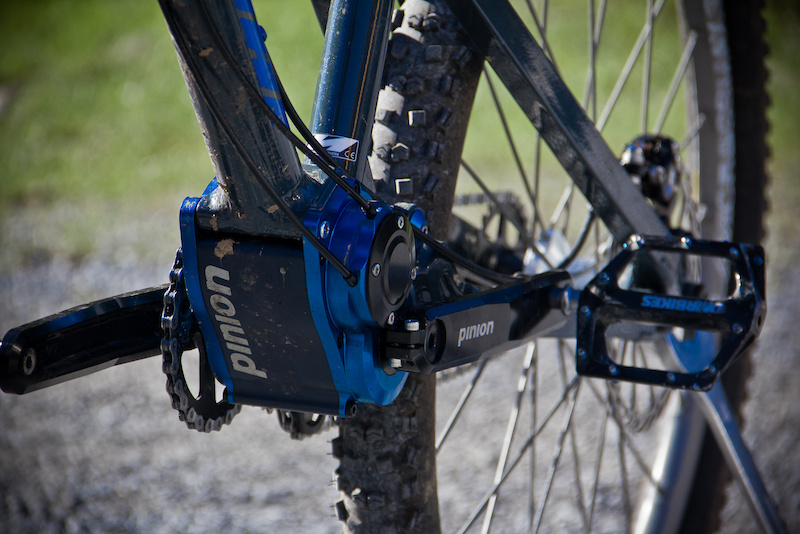
.
Last edited by safe; 02-21-13 at 11:50 AM.
02-21-13, 05:07 PM
#19
Transportation Cyclist
Thread Starter
Join Date: Aug 2011
Location: Montana U.S.A.
Posts: 1,206
Bikes: Too many to list, some I built myself including the frame. I "do" ~ Human-Only-Pedal-Powered-Cycles, Human-Electric-Hybrid-Cycles, Human-IC-Hybrid-Cycles, and one Human-IC-Electric-3way-Hybrid-Cycle
Mentioned: 0 Post(s)
Tagged: 0 Thread(s)
Quoted: 22 Post(s)
Likes: 0
Liked 0 Times
in
0 Posts
I don't disagree that personally I prefer to mount the motor(s) in the frame and run the power through the same chain as the human power. The main reason being the availability of having more then a single gear ratio, and yes the weight, and to a certain extent the efficiency as well.
It is true though that hub-motors do have some advantages to them as well though. Namely, for conversion builds, it is really quick and simple to just swap out a wheel and wire it up. In addition there is the RPM advantage. Depending on wheel size and gearing the RPM of the wheel is usually at least twice that of the crank and so there is less of a step in gearing required to match motor to wheel speed then motor to crank speed considering that all but the most obscure electric motor designs put out considerably more then 90-RPM in the peak power and efficiency ranges. Using a jack-shaft or applying the power to the chain in-between the rear wheel and crank is one way to get around this (and the method I am planning on using with this build) but never the less it is a factor. Hub-motors that are not direct drive but use an internal planetary gear reduction inside of the hub are considerably lighter weight and more efficient then direct drive hub-motors but at this time not as reliable primarily because almost every single one of them currently on the market uses weak plastic planetary gears that wear out over time and can be damaged under heavy load.
I'm talking about taking the considerably lower weight and better efficiency offered by an internal gear reduction hub motor and improving it with quality honed and lapped, heat treated steel wish-bone helical gears in the reduction stage just like top end quality internal gear hubs use to provide lifetime service with proper maintenance and smooth clean high efficiency drive. Currently almost every internal gear reduction hub motor uses cheap junk low grade rough cut simple spur steel ring and sun gear with plastic planetary gears (I've heard rumors of one that uses bronze planetary gears but have yet to track down the rumor to an actual product with that confirmed feature).
Then taking things even further and inside that hub motor along with the reduction gears include a second planetary race of internal hub gears of equal high quality construction to provide a 3-speed rotary shift standard 3:4, 1:1, 4:3 ratio spread. The power of the motor being reduced down to a usable RPM by the first stage planetary gears that matches the human input power the input sprocket on the right side of the hub for the drive chain off the crank and that combined power of the motor and the human input run through the second planetary race together which offers three switchable gear ratios to the final output to the wheel. You would need to use a slightly larger reduction ratio then standard for the first stage reduction from the motor so that your top end 4:3 ratio #3 gear on the internal hub would represent top end speed on the flat and the two lower gears would be for hill climbing.
I'm not saying I'd consider such a motor for this build since I need a wider gear range then the 177.8% that a standard ratio 3-speed IGH offers since I want to be able to haul a considerable amount of cargo up a good hill in the bottom end of the gear range and still get top speed on the flat running light with no cargo on the top end of the gear range, so that wouldn't be wide enough for my needs with this build. But if such a hub-motor existed for a regular motor assisted bike for non-cargo hauling purposes simple transportation only it could certainly be an option that could hold its own against many mid-drive arrangements breaking even on weight and efficiency and covering for its narrower gear range by its rugged compact simplicity with everything built into a compact size in the rear wheel hub, especially for upgrading a standard bike by just swapping out the rear wheel. Using a pancake disk type motor instead of radial can type motor could make it even better especially for an aerodynamic road bike with aero-wheels where the disk could be built into a smooth continuous spoke-less disk type aero-wheel.
It's and idea I've had for a while, namely nesting an internal gear hub inside of an internal gear reduction hub motor to improve its performance by offering more then one gear ratio to the drive wheel and in the process upgrading the quality of the gears by using the same quality metal gears as used in the multi-speed gearing of the hub on the reduction stage from the outer motor ring. These pancake disk motors could allow the idea to be taken even further. Wouldn't completely replace a mid-drive arrangement which still has the advantage of more gearing ratios with a wider over all range but would be far superior to current hub-motors without giving up any of the advantages of hub-motors, namely their simplicity and quick swap in set-up.
02-22-13, 10:48 AM
#20
Senior Member
Join Date: Feb 2009
Posts: 160
Mentioned: 1 Post(s)
Tagged: 0 Thread(s)
Quoted: 0 Post(s)
Likes: 0
Liked 1 Time
in
1 Post
It's also kind of funky if there is one set of gears for pedal power and another for the motor.
I like the bottom bracket location for a motor, or at least to run through the mainline gearing. But you just hinted at a disc wheel with motor built in and that's sort of where I'm going. If efficiency can be made high enough for a wheel motor across a wide enough rpm range then it could be the ideal solution. However, at 25 lbs the present hub motors are not even close to being usable. A wheel motor needs to be somewhere around 3 - 5 lbs maximum over a regular wheel and efficiency needs to be in the 92% range.
The lighter weight hub motors have low efficiency and/or weak gears.
The Gruber Assist is interesting:

...the gear drops into engagement only when you activate the motor. Otherwise it pulls up out of the way causing no friction.
.
I like the bottom bracket location for a motor, or at least to run through the mainline gearing. But you just hinted at a disc wheel with motor built in and that's sort of where I'm going. If efficiency can be made high enough for a wheel motor across a wide enough rpm range then it could be the ideal solution. However, at 25 lbs the present hub motors are not even close to being usable. A wheel motor needs to be somewhere around 3 - 5 lbs maximum over a regular wheel and efficiency needs to be in the 92% range.
The lighter weight hub motors have low efficiency and/or weak gears.
The Gruber Assist is interesting:
...the gear drops into engagement only when you activate the motor. Otherwise it pulls up out of the way causing no friction.
.
Last edited by safe; 02-22-13 at 10:53 AM.
02-22-13, 08:31 PM
#21
Transportation Cyclist
Thread Starter
Join Date: Aug 2011
Location: Montana U.S.A.
Posts: 1,206
Bikes: Too many to list, some I built myself including the frame. I "do" ~ Human-Only-Pedal-Powered-Cycles, Human-Electric-Hybrid-Cycles, Human-IC-Hybrid-Cycles, and one Human-IC-Electric-3way-Hybrid-Cycle
Mentioned: 0 Post(s)
Tagged: 0 Thread(s)
Quoted: 22 Post(s)
Likes: 0
Liked 0 Times
in
0 Posts
Yes, I entirely agree that in most cases provided you have the time and skills and are willing to put in the effort crank-drive or mid-drive is superior to hub-motors in almost every way as far as potential performance. But not everyone has the time and the skills or are willing to put in the effort and for a whole lot of people the simple "swap a wheel and then wire it up" option of a hub-motor is where they want to be. What I'm saying is that it is possible to improve the capabilities of the hub-motor option considerably while still maintaining all of its benefits in terms of quick easy install and simplicity. I just ran the numbers through my spread sheet to see what kind of a difference it could make using a hypothetical but not unrealistic set-up.
After researching some specs I set up the following test inputs for a single speed 500watt internal gear reduction rear hub motor set-up on a single speed bicycle, this is a classic hub-motor set-up just depending on the motor to power its way through the hills and head-winds (and heat up the motor running at low efficiency in the process) without attempting to use any variable ratio gearing:
I then set the following three test conditions:
And with that set-up under those test conditions this is what you get:
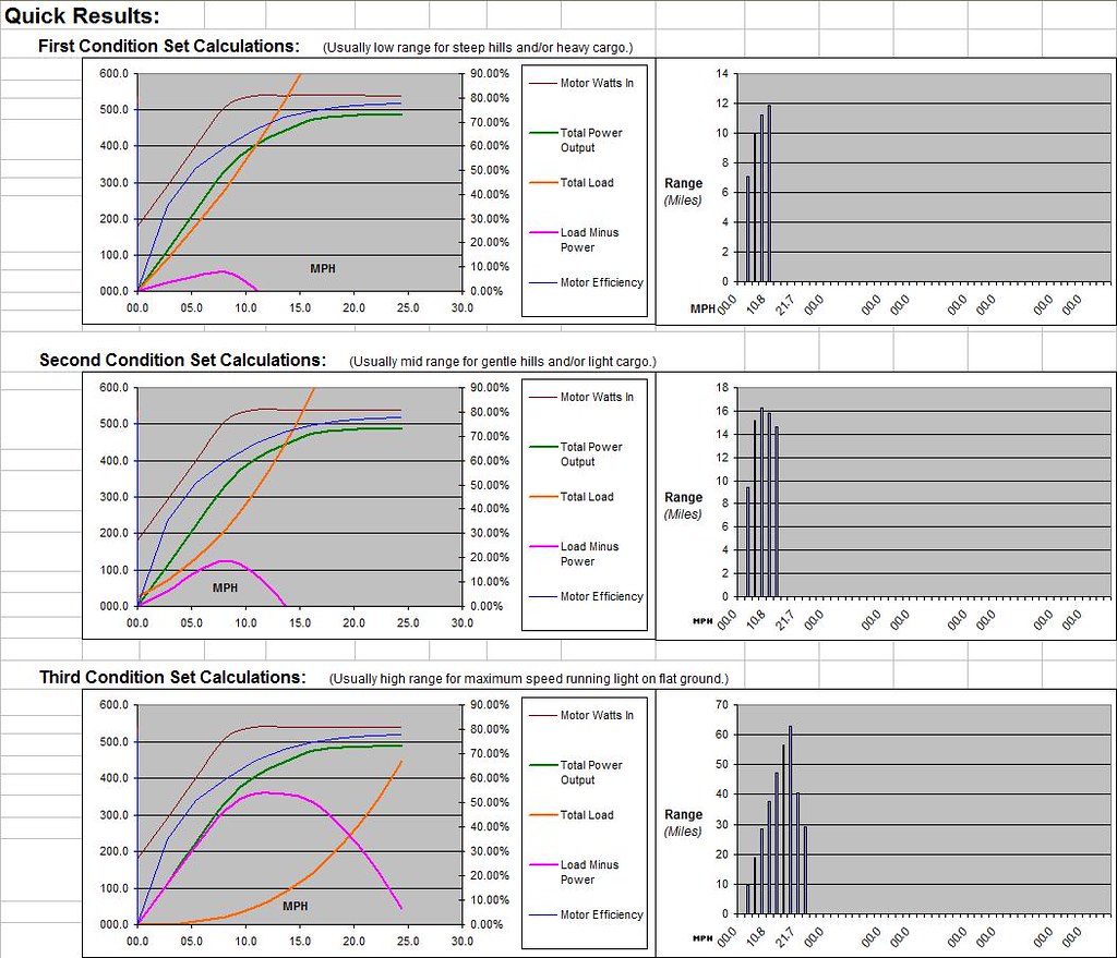
Yes, it works but you burn up a lot of power at any time you have a hill to climb or a head wind since you only have one gear for the motor.
But if you instead use that exact same hub-motor with the exact same specs only you use a 1-to-6 instead of a 1-to-4.5 internal gear reduction on the motor (so that the top #3 gearing is identical to the single speed; 1-to-6 * 4:3 = 1-to-4.5) and then run that reduced RPM motor speed and the human power input together through a 3:4, 1:1, 4:3 standard 177.8% gear range 3-speed internal gear hub that is built into the center of the same hub-motor guts you get both improved performance and improved range out of the same exact motor still all packed neatly into the hub with the same quick and easy to install capabilities with only the additional complication of the gear shifting cable mounting and adjustment and you can back the current on the motor side off to a 17.5A limit to reduce motor heating issues at the lower end of its RPM range without hindering performance:
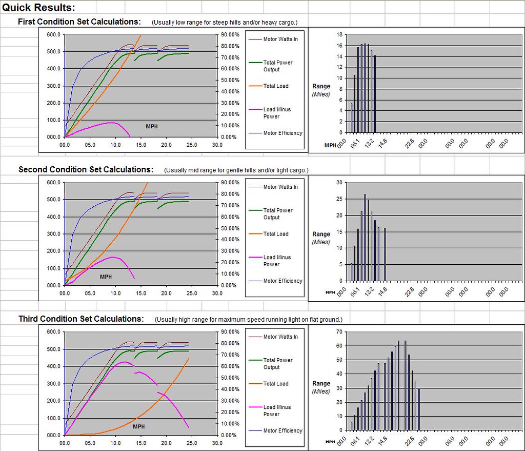
With the single speed hub-motor while climbing the 5% hill with 40-lbs. cargo the bike was capable of a range of 11.8-miles at 10.8-mph. Having the 3-speed hub gears available with everything else the same improves that to a peak range of 16.4-miles at 7.6-mph or if you don't want to go slower an improvement in both range and speed of 14.1-miles at 12.2-mph.
With the single speed hub-motor while climbing the 1% hill with a 10-mph head wind the bike was capable of a range of 16.2 miles at 8.1-mph. Having the 3-speed hub gears available with everything else the same improves that to 26.4-miles at 7.6-mph or if you don't want to go slower an improvement in both range and speed of 16.3-miles at 13.7-mph.
For running on the flat with no hill and no extra cargo and no head wind the performance is identical with the maximum range being 63-miles at 19.0-mph or a top speed of 24.4-mph with a range of 29.1-miles.
All the way around the motor in question always has an efficiency that is just barely more then 75% at its peak. But having the gears available even though its only a three speed offers a considerable improvement in performance by keeping the motor in the upper end of its efficiency range over a wider range of conditions, especially climbing hills and head winds.
So even a low efficiency stock hub motor's performance could be considerably improved by building a hybrid hub-motor with internal hub gears built into it as I suggest even if its only a simple 3-speed IGH built into the core of the hub motor.
After researching some specs I set up the following test inputs for a single speed 500watt internal gear reduction rear hub motor set-up on a single speed bicycle, this is a classic hub-motor set-up just depending on the motor to power its way through the hills and head-winds (and heat up the motor running at low efficiency in the process) without attempting to use any variable ratio gearing:
[TABLE="width: 523"]
[TR]
[TD="colspan: 2"]Gearing Ratio From Hub to Pedal Crank =[/TD]
[TD]16[/TD]
[TD]to[/TD]
[TD]42[/TD]
[/TR]
[TR]
[TD][/TD]
[TD] (Number of teeth on the rear hub sprocket then the number of teeth on the front chain ring.)[/TD]
[TD][/TD]
[TD][/TD]
[TD][/TD]
[/TR]
[TR]
[TD="colspan: 2"]Human Power Input =[/TD]
[TD]100[/TD]
[TD="colspan: 2"]watts[/TD]
[/TR]
[TR]
[TD="colspan: 2"]Mechanical Efficiency For Human Pedal Drive =[/TD]
[TD]98[/TD]
[TD="colspan: 2"]%[/TD]
[/TR]
[TR]
[TD][/TD]
[TD] (With a clean well lubricated bicycle chain at correct tension can be as high as 99%. But can be as low as 95% if set-up and condition of chain is less then ideal.)[/TD]
[TD][/TD]
[TD][/TD]
[TD][/TD]
[/TR]
[TR]
[TD][/TD]
[TD][/TD]
[TD][/TD]
[TD][/TD]
[TD][/TD]
[/TR]
[TR]
[TD][/TD]
[TD][/TD]
[TD][/TD]
[TD][/TD]
[TD][/TD]
[/TR]
[TR]
[TD][/TD]
[TD][/TD]
[TD][/TD]
[TD][/TD]
[TD][/TD]
[/TR]
[TR]
[TD="colspan: 2"]First Stage Motor Gear Reduction Ratio =[/TD]
[TD]1[/TD]
[TD]to[/TD]
[TD]4.5[/TD]
[/TR]
[TR]
[TD][/TD]
[TD] (Include the total gearing reduction between the motor's RPM and the RPM of the main range gears here.)[/TD]
[TD][/TD]
[TD][/TD]
[TD][/TD]
[/TR]
[TR]
[TD="colspan: 2"]Mechanical Efficiency of Motor Gear Reduction =[/TD]
[TD]90[/TD]
[TD="colspan: 2"]%[/TD]
[/TR]
[TR]
[TD][/TD]
[TD] (Can be as high as 99% for a clean well lubricated roller chain without idler sprockets and at correct tension. Or can be as low as 60% with some worm gear set-ups.)[/TD]
[TD][/TD]
[TD][/TD]
[TD][/TD]
[/TR]
[TR]
[TD="colspan: 2"]Motor Side Current Limit =[/TD]
[TD]30[/TD]
[TD="colspan: 2"]Amps[/TD]
[/TR]
[TR]
[TD][/TD]
[TD] (This is the maximum current as limited by the motor's controller on the motor side.)[/TD]
[TD][/TD]
[TD][/TD]
[TD][/TD]
[/TR]
[TR]
[TD="colspan: 2"]Battery Side Current Limit =[/TD]
[TD]15[/TD]
[TD="colspan: 2"]Amps[/TD]
[/TR]
[TR]
[TD][/TD]
[TD] (This is the maximum current as limited by the motor's controller on the battery side.)[/TD]
[TD][/TD]
[TD][/TD]
[TD][/TD]
[/TR]
[TR]
[TD="colspan: 2"]Motor's No Load Current =[/TD]
[TD]2.3[/TD]
[TD="colspan: 2"]Amps[/TD]
[/TR]
[TR]
[TD][/TD]
[TD] (The motors no load current at rated voltage.)[/TD]
[TD][/TD]
[TD][/TD]
[TD][/TD]
[/TR]
[TR]
[TD="colspan: 2"]Motor's Resistance =[/TD]
[TD]0.2[/TD]
[TD="colspan: 2"]Ohms[/TD]
[/TR]
[TR]
[TD][/TD]
[TD] (Rated or measured motor resistance.)[/TD]
[TD][/TD]
[TD][/TD]
[TD][/TD]
[/TR]
[TR]
[TD="colspan: 2"]Motor's Kv Rating =[/TD]
[TD]43[/TD]
[TD="colspan: 2"]Kv[/TD]
[/TR]
[TR]
[TD][/TD]
[TD] (Rated free load RPM of the motor per volt.)[/TD]
[TD][/TD]
[TD][/TD]
[TD][/TD]
[/TR]
[TR]
[TD][/TD]
[TD][/TD]
[TD][/TD]
[TD][/TD]
[TD][/TD]
[/TR]
[TR]
[TD][/TD]
[TD][/TD]
[TD][/TD]
[TD][/TD]
[TD][/TD]
[/TR]
[TR]
[TD][/TD]
[TD][/TD]
[TD][/TD]
[TD][/TD]
[TD][/TD]
[/TR]
[TR]
[TD="colspan: 2"]Actual Battery Voltage =[/TD]
[TD]36[/TD]
[TD="colspan: 2"]Volts[/TD]
[/TR]
[TR]
[TD][/TD]
[TD] (The actual real world voltage of the battery under load.)[/TD]
[TD][/TD]
[TD][/TD]
[TD][/TD]
[/TR]
[TR]
[TD="colspan: 2"]Rated Battery Capacity =[/TD]
[TD]20[/TD]
[TD="colspan: 2"]Amp-Hrs.[/TD]
[/TR]
[TR]
[TD][/TD]
[TD] (Rated battery capacity not actual usable capacity which is determined by the depth of discharge allowed which is the next input variable.)[/TD]
[TD][/TD]
[TD][/TD]
[TD][/TD]
[/TR]
[TR]
[TD="colspan: 2"]Depth of Discharge =[/TD]
[TD]80[/TD]
[TD="colspan: 2"]%[/TD]
[/TR]
[TR]
[TD][/TD]
[TD] (This is the maximum allowable depth of discharge of the battery without damaging it. For lead-acid batteries this is about 50%. For lithium batteries this is about 80%. For NiMH batteries this is 100%.)[/TD]
[TD][/TD]
[TD][/TD]
[TD][/TD]
[/TR]
[TR]
[TD][/TD]
[TD][/TD]
[TD][/TD]
[TD][/TD]
[TD][/TD]
[/TR]
[TR]
[TD][/TD]
[TD][/TD]
[TD][/TD]
[TD][/TD]
[TD][/TD]
[/TR]
[TR]
[TD][/TD]
[TD][/TD]
[TD][/TD]
[TD][/TD]
[TD][/TD]
[/TR]
[TR]
[TD="colspan: 2"]Mechanical Efficiency of Internal Hub Speed Gears =[/TD]
[TD]96[/TD]
[TD="colspan: 2"]%[/TD]
[/TR]
[TR]
[TD][/TD]
[TD] (Can be as high as 98% for a clean well lubricated bicycle chain with quality derailer set-up at correct tension. Or can be as low as 85% with some internal gear hubs.)[/TD]
[TD][/TD]
[TD][/TD]
[TD][/TD]
[/TR]
[TR]
[TD="colspan: 2"]Drive Wheel Diameter =[/TD]
[TD]26[/TD]
[TD]in[/TD]
[TD][/TD]
[/TR]
[TR]
[TD][/TD]
[TD][/TD]
[TD][/TD]
[TD][/TD]
[TD][/TD]
[/TR]
[TR]
[TD="colspan: 2"]Weight:[/TD]
[TD][/TD]
[TD][/TD]
[TD][/TD]
[/TR]
[TR]
[TD][/TD]
[TD]Bike Weight =[/TD]
[TD]80[/TD]
[TD="colspan: 2"]lbs.[/TD]
[/TR]
[TR]
[TD][/TD]
[TD]Rider Weight =[/TD]
[TD]200[/TD]
[TD="colspan: 2"]lbs.[/TD]
[/TR]
[TR]
[TD][/TD]
[TD][/TD]
[TD][/TD]
[TD][/TD]
[TD][/TD]
[/TR]
[TR]
[TD="colspan: 2"]Drag Coeficients:[/TD]
[TD][/TD]
[TD][/TD]
[TD][/TD]
[/TR]
[TR]
[TD][/TD]
[TD]Rolling Drag Coeficient =[/TD]
[TD]0.008[/TD]
[TD][/TD]
[TD][/TD]
[/TR]
[TR]
[TD][/TD]
[TD]Aerodynamic Drag Coeficient =[/TD]
[TD]0.5[/TD]
[TD][/TD]
[TD][/TD]
[/TR]
[/TABLE]
[TR]
[TD="colspan: 2"]Gearing Ratio From Hub to Pedal Crank =[/TD]
[TD]16[/TD]
[TD]to[/TD]
[TD]42[/TD]
[/TR]
[TR]
[TD][/TD]
[TD] (Number of teeth on the rear hub sprocket then the number of teeth on the front chain ring.)[/TD]
[TD][/TD]
[TD][/TD]
[TD][/TD]
[/TR]
[TR]
[TD="colspan: 2"]Human Power Input =[/TD]
[TD]100[/TD]
[TD="colspan: 2"]watts[/TD]
[/TR]
[TR]
[TD="colspan: 2"]Mechanical Efficiency For Human Pedal Drive =[/TD]
[TD]98[/TD]
[TD="colspan: 2"]%[/TD]
[/TR]
[TR]
[TD][/TD]
[TD] (With a clean well lubricated bicycle chain at correct tension can be as high as 99%. But can be as low as 95% if set-up and condition of chain is less then ideal.)[/TD]
[TD][/TD]
[TD][/TD]
[TD][/TD]
[/TR]
[TR]
[TD][/TD]
[TD][/TD]
[TD][/TD]
[TD][/TD]
[TD][/TD]
[/TR]
[TR]
[TD][/TD]
[TD][/TD]
[TD][/TD]
[TD][/TD]
[TD][/TD]
[/TR]
[TR]
[TD][/TD]
[TD][/TD]
[TD][/TD]
[TD][/TD]
[TD][/TD]
[/TR]
[TR]
[TD="colspan: 2"]First Stage Motor Gear Reduction Ratio =[/TD]
[TD]1[/TD]
[TD]to[/TD]
[TD]4.5[/TD]
[/TR]
[TR]
[TD][/TD]
[TD] (Include the total gearing reduction between the motor's RPM and the RPM of the main range gears here.)[/TD]
[TD][/TD]
[TD][/TD]
[TD][/TD]
[/TR]
[TR]
[TD="colspan: 2"]Mechanical Efficiency of Motor Gear Reduction =[/TD]
[TD]90[/TD]
[TD="colspan: 2"]%[/TD]
[/TR]
[TR]
[TD][/TD]
[TD] (Can be as high as 99% for a clean well lubricated roller chain without idler sprockets and at correct tension. Or can be as low as 60% with some worm gear set-ups.)[/TD]
[TD][/TD]
[TD][/TD]
[TD][/TD]
[/TR]
[TR]
[TD="colspan: 2"]Motor Side Current Limit =[/TD]
[TD]30[/TD]
[TD="colspan: 2"]Amps[/TD]
[/TR]
[TR]
[TD][/TD]
[TD] (This is the maximum current as limited by the motor's controller on the motor side.)[/TD]
[TD][/TD]
[TD][/TD]
[TD][/TD]
[/TR]
[TR]
[TD="colspan: 2"]Battery Side Current Limit =[/TD]
[TD]15[/TD]
[TD="colspan: 2"]Amps[/TD]
[/TR]
[TR]
[TD][/TD]
[TD] (This is the maximum current as limited by the motor's controller on the battery side.)[/TD]
[TD][/TD]
[TD][/TD]
[TD][/TD]
[/TR]
[TR]
[TD="colspan: 2"]Motor's No Load Current =[/TD]
[TD]2.3[/TD]
[TD="colspan: 2"]Amps[/TD]
[/TR]
[TR]
[TD][/TD]
[TD] (The motors no load current at rated voltage.)[/TD]
[TD][/TD]
[TD][/TD]
[TD][/TD]
[/TR]
[TR]
[TD="colspan: 2"]Motor's Resistance =[/TD]
[TD]0.2[/TD]
[TD="colspan: 2"]Ohms[/TD]
[/TR]
[TR]
[TD][/TD]
[TD] (Rated or measured motor resistance.)[/TD]
[TD][/TD]
[TD][/TD]
[TD][/TD]
[/TR]
[TR]
[TD="colspan: 2"]Motor's Kv Rating =[/TD]
[TD]43[/TD]
[TD="colspan: 2"]Kv[/TD]
[/TR]
[TR]
[TD][/TD]
[TD] (Rated free load RPM of the motor per volt.)[/TD]
[TD][/TD]
[TD][/TD]
[TD][/TD]
[/TR]
[TR]
[TD][/TD]
[TD][/TD]
[TD][/TD]
[TD][/TD]
[TD][/TD]
[/TR]
[TR]
[TD][/TD]
[TD][/TD]
[TD][/TD]
[TD][/TD]
[TD][/TD]
[/TR]
[TR]
[TD][/TD]
[TD][/TD]
[TD][/TD]
[TD][/TD]
[TD][/TD]
[/TR]
[TR]
[TD="colspan: 2"]Actual Battery Voltage =[/TD]
[TD]36[/TD]
[TD="colspan: 2"]Volts[/TD]
[/TR]
[TR]
[TD][/TD]
[TD] (The actual real world voltage of the battery under load.)[/TD]
[TD][/TD]
[TD][/TD]
[TD][/TD]
[/TR]
[TR]
[TD="colspan: 2"]Rated Battery Capacity =[/TD]
[TD]20[/TD]
[TD="colspan: 2"]Amp-Hrs.[/TD]
[/TR]
[TR]
[TD][/TD]
[TD] (Rated battery capacity not actual usable capacity which is determined by the depth of discharge allowed which is the next input variable.)[/TD]
[TD][/TD]
[TD][/TD]
[TD][/TD]
[/TR]
[TR]
[TD="colspan: 2"]Depth of Discharge =[/TD]
[TD]80[/TD]
[TD="colspan: 2"]%[/TD]
[/TR]
[TR]
[TD][/TD]
[TD] (This is the maximum allowable depth of discharge of the battery without damaging it. For lead-acid batteries this is about 50%. For lithium batteries this is about 80%. For NiMH batteries this is 100%.)[/TD]
[TD][/TD]
[TD][/TD]
[TD][/TD]
[/TR]
[TR]
[TD][/TD]
[TD][/TD]
[TD][/TD]
[TD][/TD]
[TD][/TD]
[/TR]
[TR]
[TD][/TD]
[TD][/TD]
[TD][/TD]
[TD][/TD]
[TD][/TD]
[/TR]
[TR]
[TD][/TD]
[TD][/TD]
[TD][/TD]
[TD][/TD]
[TD][/TD]
[/TR]
[TR]
[TD="colspan: 2"]Mechanical Efficiency of Internal Hub Speed Gears =[/TD]
[TD]96[/TD]
[TD="colspan: 2"]%[/TD]
[/TR]
[TR]
[TD][/TD]
[TD] (Can be as high as 98% for a clean well lubricated bicycle chain with quality derailer set-up at correct tension. Or can be as low as 85% with some internal gear hubs.)[/TD]
[TD][/TD]
[TD][/TD]
[TD][/TD]
[/TR]
[TR]
[TD="colspan: 2"]Drive Wheel Diameter =[/TD]
[TD]26[/TD]
[TD]in[/TD]
[TD][/TD]
[/TR]
[TR]
[TD][/TD]
[TD][/TD]
[TD][/TD]
[TD][/TD]
[TD][/TD]
[/TR]
[TR]
[TD="colspan: 2"]Weight:[/TD]
[TD][/TD]
[TD][/TD]
[TD][/TD]
[/TR]
[TR]
[TD][/TD]
[TD]Bike Weight =[/TD]
[TD]80[/TD]
[TD="colspan: 2"]lbs.[/TD]
[/TR]
[TR]
[TD][/TD]
[TD]Rider Weight =[/TD]
[TD]200[/TD]
[TD="colspan: 2"]lbs.[/TD]
[/TR]
[TR]
[TD][/TD]
[TD][/TD]
[TD][/TD]
[TD][/TD]
[TD][/TD]
[/TR]
[TR]
[TD="colspan: 2"]Drag Coeficients:[/TD]
[TD][/TD]
[TD][/TD]
[TD][/TD]
[/TR]
[TR]
[TD][/TD]
[TD]Rolling Drag Coeficient =[/TD]
[TD]0.008[/TD]
[TD][/TD]
[TD][/TD]
[/TR]
[TR]
[TD][/TD]
[TD]Aerodynamic Drag Coeficient =[/TD]
[TD]0.5[/TD]
[TD][/TD]
[TD][/TD]
[/TR]
[/TABLE]
I then set the following three test conditions:
[TABLE="width: 715"]
[TR]
[TD="colspan: 8"] First Condition Set Calculations: (Usually low range for steep hills and/or heavy cargo.)[/TD]
[/TR]
[TR]
[TD][/TD]
[TD="colspan: 2"]Additional Cargo weight =[/TD]
[TD]40[/TD]
[TD="colspan: 2"]lbs.[/TD]
[TD][/TD]
[TD][/TD]
[/TR]
[TR]
[TD][/TD]
[TD="colspan: 2"]Hill Grade =[/TD]
[TD]5[/TD]
[TD="colspan: 2"]%[/TD]
[TD][/TD]
[TD][/TD]
[/TR]
[TR]
[TD][/TD]
[TD="colspan: 2"]Head Wind (or tail wind) =[/TD]
[TD]0[/TD]
[TD="colspan: 2"]MPH[/TD]
[TD][/TD]
[TD][/TD]
[/TR]
[TR]
[TD][/TD]
[TD][/TD]
[TD] (Positive number for head wind and negative for tail wind.)[/TD]
[TD][/TD]
[TD][/TD]
[TD][/TD]
[TD][/TD]
[TD][/TD]
[/TR]
[TR]
[TD][/TD]
[TD][/TD]
[TD][/TD]
[TD][/TD]
[TD][/TD]
[TD][/TD]
[TD][/TD]
[TD][/TD]
[/TR]
[TR]
[TD="colspan: 8"] Second Condition Set Calculations: (Usually mid range for gentle hills and/or light cargo.)[/TD]
[/TR]
[TR]
[TD][/TD]
[TD="colspan: 2"]Additional Cargo weight =[/TD]
[TD]0[/TD]
[TD="colspan: 2"]lbs.[/TD]
[TD][/TD]
[TD][/TD]
[/TR]
[TR]
[TD][/TD]
[TD="colspan: 2"]Hill Grade =[/TD]
[TD]1[/TD]
[TD="colspan: 2"]%[/TD]
[TD][/TD]
[TD][/TD]
[/TR]
[TR]
[TD][/TD]
[TD="colspan: 2"]Head Wind (or tail wind) =[/TD]
[TD]10[/TD]
[TD="colspan: 2"]MPH[/TD]
[TD][/TD]
[TD][/TD]
[/TR]
[TR]
[TD][/TD]
[TD][/TD]
[TD] (Positive number for head wind and negative for tail wind.)[/TD]
[TD][/TD]
[TD][/TD]
[TD][/TD]
[TD][/TD]
[TD][/TD]
[/TR]
[TR]
[TD][/TD]
[TD][/TD]
[TD][/TD]
[TD][/TD]
[TD][/TD]
[TD][/TD]
[TD][/TD]
[TD][/TD]
[/TR]
[TR]
[TD="colspan: 8"] Third Condition Set Calculations: (Usually high range for maximum speed running light on flat ground.)[/TD]
[/TR]
[TR]
[TD][/TD]
[TD="colspan: 2"]Additional Cargo weight =[/TD]
[TD]0[/TD]
[TD="colspan: 2"]lbs.[/TD]
[TD][/TD]
[TD][/TD]
[/TR]
[TR]
[TD][/TD]
[TD="colspan: 2"]Hill Grade =[/TD]
[TD]0[/TD]
[TD="colspan: 2"]%[/TD]
[TD][/TD]
[TD][/TD]
[/TR]
[TR]
[TD][/TD]
[TD="colspan: 2"]Head Wind (or tail wind) =[/TD]
[TD]0[/TD]
[TD="colspan: 2"]MPH[/TD]
[TD][/TD]
[TD][/TD]
[/TR]
[TR]
[TD][/TD]
[TD][/TD]
[TD] (Positive number for head wind and negative for tail wind.)[/TD]
[TD][/TD]
[TD][/TD]
[TD][/TD]
[TD][/TD]
[TD][/TD]
[/TR]
[/TABLE]
[TR]
[TD="colspan: 8"] First Condition Set Calculations: (Usually low range for steep hills and/or heavy cargo.)[/TD]
[/TR]
[TR]
[TD][/TD]
[TD="colspan: 2"]Additional Cargo weight =[/TD]
[TD]40[/TD]
[TD="colspan: 2"]lbs.[/TD]
[TD][/TD]
[TD][/TD]
[/TR]
[TR]
[TD][/TD]
[TD="colspan: 2"]Hill Grade =[/TD]
[TD]5[/TD]
[TD="colspan: 2"]%[/TD]
[TD][/TD]
[TD][/TD]
[/TR]
[TR]
[TD][/TD]
[TD="colspan: 2"]Head Wind (or tail wind) =[/TD]
[TD]0[/TD]
[TD="colspan: 2"]MPH[/TD]
[TD][/TD]
[TD][/TD]
[/TR]
[TR]
[TD][/TD]
[TD][/TD]
[TD] (Positive number for head wind and negative for tail wind.)[/TD]
[TD][/TD]
[TD][/TD]
[TD][/TD]
[TD][/TD]
[TD][/TD]
[/TR]
[TR]
[TD][/TD]
[TD][/TD]
[TD][/TD]
[TD][/TD]
[TD][/TD]
[TD][/TD]
[TD][/TD]
[TD][/TD]
[/TR]
[TR]
[TD="colspan: 8"] Second Condition Set Calculations: (Usually mid range for gentle hills and/or light cargo.)[/TD]
[/TR]
[TR]
[TD][/TD]
[TD="colspan: 2"]Additional Cargo weight =[/TD]
[TD]0[/TD]
[TD="colspan: 2"]lbs.[/TD]
[TD][/TD]
[TD][/TD]
[/TR]
[TR]
[TD][/TD]
[TD="colspan: 2"]Hill Grade =[/TD]
[TD]1[/TD]
[TD="colspan: 2"]%[/TD]
[TD][/TD]
[TD][/TD]
[/TR]
[TR]
[TD][/TD]
[TD="colspan: 2"]Head Wind (or tail wind) =[/TD]
[TD]10[/TD]
[TD="colspan: 2"]MPH[/TD]
[TD][/TD]
[TD][/TD]
[/TR]
[TR]
[TD][/TD]
[TD][/TD]
[TD] (Positive number for head wind and negative for tail wind.)[/TD]
[TD][/TD]
[TD][/TD]
[TD][/TD]
[TD][/TD]
[TD][/TD]
[/TR]
[TR]
[TD][/TD]
[TD][/TD]
[TD][/TD]
[TD][/TD]
[TD][/TD]
[TD][/TD]
[TD][/TD]
[TD][/TD]
[/TR]
[TR]
[TD="colspan: 8"] Third Condition Set Calculations: (Usually high range for maximum speed running light on flat ground.)[/TD]
[/TR]
[TR]
[TD][/TD]
[TD="colspan: 2"]Additional Cargo weight =[/TD]
[TD]0[/TD]
[TD="colspan: 2"]lbs.[/TD]
[TD][/TD]
[TD][/TD]
[/TR]
[TR]
[TD][/TD]
[TD="colspan: 2"]Hill Grade =[/TD]
[TD]0[/TD]
[TD="colspan: 2"]%[/TD]
[TD][/TD]
[TD][/TD]
[/TR]
[TR]
[TD][/TD]
[TD="colspan: 2"]Head Wind (or tail wind) =[/TD]
[TD]0[/TD]
[TD="colspan: 2"]MPH[/TD]
[TD][/TD]
[TD][/TD]
[/TR]
[TR]
[TD][/TD]
[TD][/TD]
[TD] (Positive number for head wind and negative for tail wind.)[/TD]
[TD][/TD]
[TD][/TD]
[TD][/TD]
[TD][/TD]
[TD][/TD]
[/TR]
[/TABLE]
And with that set-up under those test conditions this is what you get:
Yes, it works but you burn up a lot of power at any time you have a hill to climb or a head wind since you only have one gear for the motor.
But if you instead use that exact same hub-motor with the exact same specs only you use a 1-to-6 instead of a 1-to-4.5 internal gear reduction on the motor (so that the top #3 gearing is identical to the single speed; 1-to-6 * 4:3 = 1-to-4.5) and then run that reduced RPM motor speed and the human power input together through a 3:4, 1:1, 4:3 standard 177.8% gear range 3-speed internal gear hub that is built into the center of the same hub-motor guts you get both improved performance and improved range out of the same exact motor still all packed neatly into the hub with the same quick and easy to install capabilities with only the additional complication of the gear shifting cable mounting and adjustment and you can back the current on the motor side off to a 17.5A limit to reduce motor heating issues at the lower end of its RPM range without hindering performance:
With the single speed hub-motor while climbing the 5% hill with 40-lbs. cargo the bike was capable of a range of 11.8-miles at 10.8-mph. Having the 3-speed hub gears available with everything else the same improves that to a peak range of 16.4-miles at 7.6-mph or if you don't want to go slower an improvement in both range and speed of 14.1-miles at 12.2-mph.
With the single speed hub-motor while climbing the 1% hill with a 10-mph head wind the bike was capable of a range of 16.2 miles at 8.1-mph. Having the 3-speed hub gears available with everything else the same improves that to 26.4-miles at 7.6-mph or if you don't want to go slower an improvement in both range and speed of 16.3-miles at 13.7-mph.
For running on the flat with no hill and no extra cargo and no head wind the performance is identical with the maximum range being 63-miles at 19.0-mph or a top speed of 24.4-mph with a range of 29.1-miles.
All the way around the motor in question always has an efficiency that is just barely more then 75% at its peak. But having the gears available even though its only a three speed offers a considerable improvement in performance by keeping the motor in the upper end of its efficiency range over a wider range of conditions, especially climbing hills and head winds.
So even a low efficiency stock hub motor's performance could be considerably improved by building a hybrid hub-motor with internal hub gears built into it as I suggest even if its only a simple 3-speed IGH built into the core of the hub motor.
02-22-13, 08:53 PM
#22
Transportation Cyclist
Thread Starter
Join Date: Aug 2011
Location: Montana U.S.A.
Posts: 1,206
Bikes: Too many to list, some I built myself including the frame. I "do" ~ Human-Only-Pedal-Powered-Cycles, Human-Electric-Hybrid-Cycles, Human-IC-Hybrid-Cycles, and one Human-IC-Electric-3way-Hybrid-Cycle
Mentioned: 0 Post(s)
Tagged: 0 Thread(s)
Quoted: 22 Post(s)
Likes: 0
Liked 0 Times
in
0 Posts
As to the Gruber Assist, yes an excellent "stealth" crank drive set-up since the motor and drive to the crank is installed in the seat-post tube. Some people go so far as to refer to that particular set-up not only as "stealth" but rather a "cheater" set-up. As I said, I like crank/mid drive set-ups as well. Its just I'm willing to consider other set-ups as well. I'll even consider friction drives in a few situations although they are probably my least favorite and only suitable for use on road-bikes with slick tires in nice dry sunny weather in my opinion (look up "Commuter Booster" in an internet search for more info).
As to set-ups that have different gears for pedal and motor power. That could be workable but not anywhere near ideal in my opinion and could get confusing. It could be better then only a single gear ratio though. On my bike with a Staton-Inc axle mount 1.6hp 35cc mini 4-cycle motor I wouldn't mind having just two speeds on the motor drive instead of just a single gear ratio. Since gas motors are much more gutless in the bottom of their RPM range then even the most inefficient and badly designed electric motor set-up when climbing a hill if you don't put in enough pedal power to keep yourself moving fast enough for the motor to not get bogged down you can end up SOL with a bogged down motor that isn't helping hardly at all and you have to just pedal until you get to the top of the hill and can get up enough speed to get the motor back into its power range in the upper RPMs. I've got a full set of 21 pedal speeds on that bike and no motor speeds just a single drive ratio for the motor. When in town in stop and go traffic when I don't have the time to constantly shift up and down through the pedal gear range I leave the pedals in a lower gear ratio and use pedal power to accelerate from a stop till I'm going fast enough for the motor to take over then I punch the throttle on the motor (which I just leave idling until up to speed) and stop pedaling because I can't pedal at high enough cadence to keep up without shifting up in the pedal gears. So it is set up kind of like your road racer build, safe, in that you pedal from a stop up to a speed where the motor takes over and then stop pedaling at higher speeds. When I'm cruising over distance then I gear up in the pedal drive to match the motor speed and add my pedal power to the mix to get a little more speed and get a little better mileage (strong pedaling along with the motor at speed boosts the top speed on the flat from about 22 to 25 mph and increases the gas mileage from a little over 100-mpg to just barely under 150-mpg on that bike). I do wish though that I just had two seperate gears on the motor drive. A "low" gear for ascending sizable hills that normally could drag down my speed till the gas motor isn't helping anymore, and a "high" gear for on the flat. Having an extra gear lever on the handlebars, or maybe even one of those old style road bike shifters mounted on the top tube of the frame would be worth it. Even better would be a way to rig up the motor gears so that when I was in the big #3 front chain ring the motor was in its "high" gear and when I shifted down into either the #2 or #1 front chain ring it would also shift the motor gears into the "low" gear. I think that would take a lot of work to set-up though since the motor drive on the left side of the rear hub uses #35 chain which is pretty wide and laterally stiff and hard to shift derailer style and there isn't room to try to do it any other way.
As to set-ups that have different gears for pedal and motor power. That could be workable but not anywhere near ideal in my opinion and could get confusing. It could be better then only a single gear ratio though. On my bike with a Staton-Inc axle mount 1.6hp 35cc mini 4-cycle motor I wouldn't mind having just two speeds on the motor drive instead of just a single gear ratio. Since gas motors are much more gutless in the bottom of their RPM range then even the most inefficient and badly designed electric motor set-up when climbing a hill if you don't put in enough pedal power to keep yourself moving fast enough for the motor to not get bogged down you can end up SOL with a bogged down motor that isn't helping hardly at all and you have to just pedal until you get to the top of the hill and can get up enough speed to get the motor back into its power range in the upper RPMs. I've got a full set of 21 pedal speeds on that bike and no motor speeds just a single drive ratio for the motor. When in town in stop and go traffic when I don't have the time to constantly shift up and down through the pedal gear range I leave the pedals in a lower gear ratio and use pedal power to accelerate from a stop till I'm going fast enough for the motor to take over then I punch the throttle on the motor (which I just leave idling until up to speed) and stop pedaling because I can't pedal at high enough cadence to keep up without shifting up in the pedal gears. So it is set up kind of like your road racer build, safe, in that you pedal from a stop up to a speed where the motor takes over and then stop pedaling at higher speeds. When I'm cruising over distance then I gear up in the pedal drive to match the motor speed and add my pedal power to the mix to get a little more speed and get a little better mileage (strong pedaling along with the motor at speed boosts the top speed on the flat from about 22 to 25 mph and increases the gas mileage from a little over 100-mpg to just barely under 150-mpg on that bike). I do wish though that I just had two seperate gears on the motor drive. A "low" gear for ascending sizable hills that normally could drag down my speed till the gas motor isn't helping anymore, and a "high" gear for on the flat. Having an extra gear lever on the handlebars, or maybe even one of those old style road bike shifters mounted on the top tube of the frame would be worth it. Even better would be a way to rig up the motor gears so that when I was in the big #3 front chain ring the motor was in its "high" gear and when I shifted down into either the #2 or #1 front chain ring it would also shift the motor gears into the "low" gear. I think that would take a lot of work to set-up though since the motor drive on the left side of the rear hub uses #35 chain which is pretty wide and laterally stiff and hard to shift derailer style and there isn't room to try to do it any other way.
02-22-13, 09:55 PM
#23
Senior Member
Join Date: Feb 2009
Posts: 160
Mentioned: 1 Post(s)
Tagged: 0 Thread(s)
Quoted: 0 Post(s)
Likes: 0
Liked 1 Time
in
1 Post
My first ebike (Project #001) ran the motor power through a derailler and so it had six gears.
I did a total of 10,000 miles (really) on that ebike.
Technically it wasn't a bicycle though because it didn't use pedals. Where I was living it was legal, but when I moved I decided to sell/give away the bike to someone who lived in the area.
So I totally agree on gears.
In a sense gears are almost "too good" because you never need to pedal. For a "Road Racer" concept where you find yourself never needing to pedal because you already are going too fast it made sense to switch to a more limiting single speed and "Force Limiting" setup.
Gears amplify torque and that means faster acceleration or climbing... so if there is "too much" of it the sporting concept disappears.
With gears you usually don't overheat. (an added benefit)
.
Last edited by safe; 02-22-13 at 09:59 PM.
02-25-13, 08:13 AM
#24
Member
Join Date: Sep 2012
Location: Toronto
Posts: 28
Bikes: Alex Moulton 7, Opus Zermatt/BionX 350, Epik Whistler
Mentioned: 0 Post(s)
Tagged: 0 Thread(s)
Quoted: 0 Post(s)
Likes: 0
Liked 0 Times
in
0 Posts
Your design looks a lot like My Moulton.
02-25-13, 10:31 AM
#25
Senior Member
Join Date: Jun 2011
Location: Bend, OR
Posts: 85
Mentioned: 0 Post(s)
Tagged: 0 Thread(s)
Quoted: 0 Post(s)
Likes: 0
Liked 0 Times
in
0 Posts
Yes, i love the moulton design. This looks a lot like it. Not as much of a trellis design. Although it is sort of a mixte, with the seat stays running parallel all the way to the head tube.
Here's the latest version of the design, now it looks perhaps more like an Enfield Revelation:
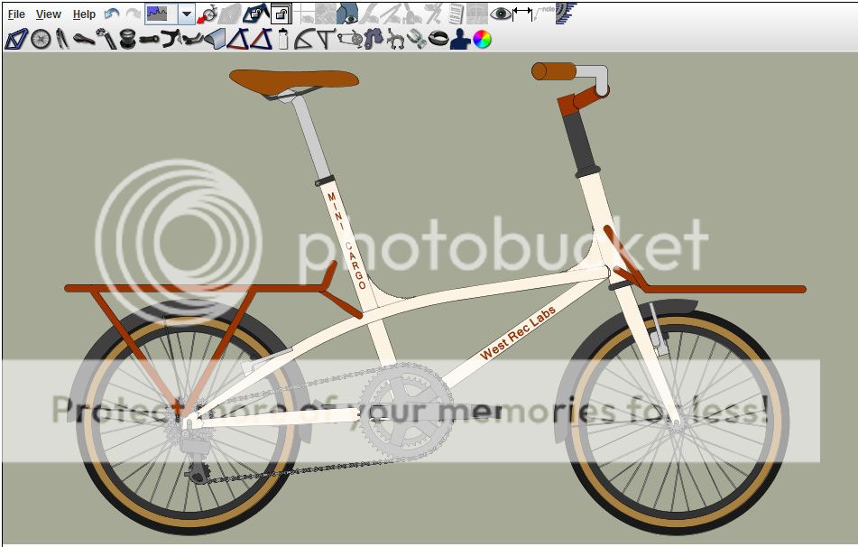
Here's the latest version of the design, now it looks perhaps more like an Enfield Revelation: