


My DIY Blinkie, with Planet Bike Super Flash comparison pics
 01-26-08, 02:17 PM
#1
?
Thread Starter
Join Date: Oct 2006
Posts: 2,775
Mentioned: 0 Post(s)
Tagged: 0 Thread(s)
Quoted: 0 Post(s)
Likes: 0
Liked 0 Times
in
0 Posts
My DIY Blinkie, with Planet Bike Super Flash comparison pics
This is a double post from Commuting subforums.
https://bikeforums.net/showthread.php?t=381557
My Dinotte style Blinkie.
Size comparison with PB SF, sorry for the crappy photo.
The led does get hot, thus I used an aluminum plate that was for scraps.
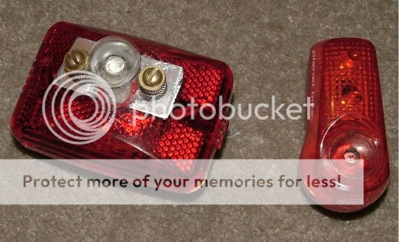
I should have spent more time making it neat, but oh well, it took me about 30 minutes to make this.
PB SF on the left, my DIY on the right on high mode. On low mode, it is just as bright as the SF but with a really wide beam.

The beam's hotspot and flood is very very wide.
Cost:
Cree XR Red led, $5
5-mode driver (10Hz flashing, SOS, high, medium, low), $3.10
30� Lens for LUXIII, drilled and sanded to fit Cree, $1.40
Clicky switch, $0.30
I got all of the above from kaidomain.com
+ miscellaneous (wires, solder, silicone sealant, nuts, screws, presta valve thread nuts (from punctured tires))
Total: $10 + old parts
The case is from an old Vistalite, I tried to fit the LED inside the casing, but the led got really hot.
Edit: more info added
The light mounts on a standard Planet bike mount for the BRT3, BRT7, and the SF, I use this mount because I have this mount on all of my bikes. I was a SF fanboy (I currently own 3 SF), but not anymore, this thing has +180� visibility when flashing because the lens is not covered, PBSF is a joke compared to this monster.
It takes 2 AA, I have no idea what the run time will be, so I'll be testing this light tomorrow night. I will be running this light flashing while PBSF will be on steady..
https://bikeforums.net/showthread.php?t=381557
My Dinotte style Blinkie.
Size comparison with PB SF, sorry for the crappy photo.
The led does get hot, thus I used an aluminum plate that was for scraps.
I should have spent more time making it neat, but oh well, it took me about 30 minutes to make this.
PB SF on the left, my DIY on the right on high mode. On low mode, it is just as bright as the SF but with a really wide beam.
The beam's hotspot and flood is very very wide.
Cost:
Cree XR Red led, $5
5-mode driver (10Hz flashing, SOS, high, medium, low), $3.10
30� Lens for LUXIII, drilled and sanded to fit Cree, $1.40
Clicky switch, $0.30
I got all of the above from kaidomain.com
+ miscellaneous (wires, solder, silicone sealant, nuts, screws, presta valve thread nuts (from punctured tires))
Total: $10 + old parts
The case is from an old Vistalite, I tried to fit the LED inside the casing, but the led got really hot.
Edit: more info added
The light mounts on a standard Planet bike mount for the BRT3, BRT7, and the SF, I use this mount because I have this mount on all of my bikes. I was a SF fanboy (I currently own 3 SF), but not anymore, this thing has +180� visibility when flashing because the lens is not covered, PBSF is a joke compared to this monster.
It takes 2 AA, I have no idea what the run time will be, so I'll be testing this light tomorrow night. I will be running this light flashing while PBSF will be on steady..
 02-14-08, 08:47 PM
#2

Dirt Bomb

Join Date: Aug 2006
Location: Illinois
Posts: 2,865
Mentioned: 64 Post(s)
Tagged: 0 Thread(s)
Quoted: 5464 Post(s)
Liked 288 Times
in
239 Posts
Mr. B.,
I got my circuit board and lens in the mail today. Still waiting on the led and switch.
Do you have a wiring diagram, or know where I can get one for this circuit?
Much thanks.
I got my circuit board and lens in the mail today. Still waiting on the led and switch.
Do you have a wiring diagram, or know where I can get one for this circuit?
Much thanks.
__________________

 02-16-08, 07:37 PM
#8

Zoom zoom zoom zoom bonk

Join Date: Sep 2006
Location: New Zealand
Posts: 4,624
Bikes: Giant Defy, Trek 1.7c, BMC GF02, Fuji Tahoe, Scott Sub 35, Kona Rove, Trek Verve+2
Mentioned: 6 Post(s)
Tagged: 0 Thread(s)
Quoted: 551 Post(s)
Liked 722 Times
in
366 Posts
How is the runtime?
02-16-08, 11:13 PM
#9
?
Thread Starter
Join Date: Oct 2006
Posts: 2,775
Mentioned: 0 Post(s)
Tagged: 0 Thread(s)
Quoted: 0 Post(s)
Likes: 0
Liked 0 Times
in
0 Posts
With 2500mAH Sanyo batteries.
Flashing, 3.5 hours.
High, about 2.5 hours. I have not tested medium and low yet, I have calculated it would be 7 hours on medium and 17 hours on low.
Given the runtime is really poor. I have considered a 4AA battery pack that is wired in parallel. At the moment, I'm quite satisfied.
Flashing, 3.5 hours.
High, about 2.5 hours. I have not tested medium and low yet, I have calculated it would be 7 hours on medium and 17 hours on low.
Given the runtime is really poor. I have considered a 4AA battery pack that is wired in parallel. At the moment, I'm quite satisfied.
02-19-08, 08:53 PM
#10
Dirt Bomb
Join Date: Aug 2006
Location: Illinois
Posts: 2,865
Mentioned: 64 Post(s)
Tagged: 0 Thread(s)
Quoted: 5464 Post(s)
Liked 288 Times
in
239 Posts
I put a continuity tester between D1 and the inner circle on back and got continuity.
I put the tester between Q3 and the outer ring and got continuity.
So.....I take it that the circuit board had only two leads, and the diode has two leads, and they are hooked up in series with each other and the battery?
Is there anywhere to get a wiring diagram or schematic for this circuit?
I put the tester between Q3 and the outer ring and got continuity.
So.....I take it that the circuit board had only two leads, and the diode has two leads, and they are hooked up in series with each other and the battery?
Is there anywhere to get a wiring diagram or schematic for this circuit?
__________________
03-03-08, 09:32 PM
#12
Dirt Bomb
Join Date: Aug 2006
Location: Illinois
Posts: 2,865
Mentioned: 64 Post(s)
Tagged: 0 Thread(s)
Quoted: 5464 Post(s)
Liked 288 Times
in
239 Posts
My circuit works! I soldered leads to all the components then I plugged them into a breadboard. It's very bright. Now I need to figure out a way to mount it in a housing. I temporarily fixed the led to a piece of square aluminum tubing to act as a heat sink. Now that I know it works I will build something to hold it all together. I'll post some pics when I get time.
I need to find some little tiny self-tapping screws. I'll probably rob them off an old junk computer or something.
Thanks Mr. Bubbles
I need to find some little tiny self-tapping screws. I'll probably rob them off an old junk computer or something.
Thanks Mr. Bubbles
__________________
03-03-08, 11:13 PM
#13
?
Thread Starter
Join Date: Oct 2006
Posts: 2,775
Mentioned: 0 Post(s)
Tagged: 0 Thread(s)
Quoted: 0 Post(s)
Likes: 0
Liked 0 Times
in
0 Posts
Just wait until I build up a 4 Cree XR led powered by 4AA later this year after the summer is over. It's possible I might even feel antsy and build it before summer arrives.
03-09-08, 12:31 AM
#14
Dirt Bomb
Join Date: Aug 2006
Location: Illinois
Posts: 2,865
Mentioned: 64 Post(s)
Tagged: 0 Thread(s)
Quoted: 5464 Post(s)
Liked 288 Times
in
239 Posts
Hey, I got mine finished - well, wired up anyway. I'm still getting it all stuffed into the housing.
Got one question; How do you switch between modes? I've been randomly clicking the switch but haven't discovered the definite sequence for switching modes.
Help!
Got one question; How do you switch between modes? I've been randomly clicking the switch but haven't discovered the definite sequence for switching modes.
Help!
