Frame alignment questions
 02-21-13, 12:57 PM
#1
Member
Thread Starter
Join Date: Jan 2013
Posts: 47
Mentioned: 0 Post(s)
Tagged: 0 Thread(s)
Quoted: 0 Post(s)
Likes: 0
Liked 0 Times
in
0 Posts
Frame alignment questions
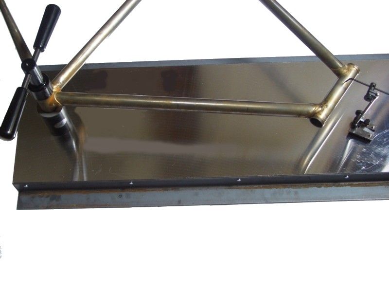
So I'm in the process of starting my first frame build and I've been putting together Jig ideas, tooling, and measurement processes.
On that measurement process, I found my granite island counter top to be incredibly flat. My question is, based on this picture, does this appear to be a fairly accurate way of measurement. Obviously this BB has been faced, which helps with my clamp mounts. The frame here checks out within .15mm on all tube measurements except the TT, which angles up .65mm from ST to HT. Seems like a lot, but maybe my process is flawed??
I checked another frame using this method and found it consistent all around, no more than .2mm out, so I think the table and mounting method is ok, but what do I know..
Thoughts?
 02-21-13, 01:16 PM
#2


Randomhead
Join Date: Aug 2008
Location: Happy Valley, Pennsylvania
Posts: 24,386
Mentioned: 0 Post(s)
Tagged: 0 Thread(s)
Quoted: 4 Post(s)
Liked 3,686 Times
in
2,509 Posts
.65mm is pretty good, if you have your decimal point in the right place. I think most people quote 1mm if they say anything at all. Cantilevering off of the BB shell contributes a lot of that, you are measuring a lot of errors. As point of reference, a large U.S. brand of bikes says 5mm is ok.
Steel tubes are often off at least 1mm over their length depending on your reference.
For low-tech measuring, I think putting the head tube on a rod between v-blocks is probably a better method. It's really easy to get off a little referencing to the bb shell and then where does that leave you? The bb shell distorts quite a bit during brazing/welding
02-21-13, 02:26 PM
#3

Senior Member

Join Date: Mar 2012
Location: santa barbara CA
Posts: 1,087
Mentioned: 1 Post(s)
Tagged: 0 Thread(s)
Quoted: 96 Post(s)
Liked 30 Times
in
21 Posts
Interesting. Why not use a granite piece like this for a surface plate? I don't know how you would measure one for flatness but if its within .005 to .010 why not? I realize this isn't inspection plate spec such as .0004 but how flat does it need to be? That's really my questgion, just what tolerances are needed/necessay for a surface plate used in frame building?
thanks, Brian
thanks, Brian
__________________
Brian
Brian
Last edited by calstar; 02-21-13 at 02:31 PM.
02-21-13, 03:17 PM
#4
Member
Thread Starter
Join Date: Jan 2013
Posts: 47
Mentioned: 0 Post(s)
Tagged: 0 Thread(s)
Quoted: 0 Post(s)
Likes: 0
Liked 0 Times
in
0 Posts
.65mm is pretty good, if you have your decimal point in the right place. I think most people quote 1mm if they say anything at all. Cantilevering off of the BB shell contributes a lot of that, you are measuring a lot of errors. As point of reference, a large U.S. brand of bikes says 5mm is ok.
Steel tubes are often off at least 1mm over their length depending on your reference.
For low-tech measuring, I think putting the head tube on a rod between v-blocks is probably a better method. It's really easy to get off a little referencing to the bb shell and then where does that leave you? The bb shell distorts quite a bit during brazing/welding
Steel tubes are often off at least 1mm over their length depending on your reference.
For low-tech measuring, I think putting the head tube on a rod between v-blocks is probably a better method. It's really easy to get off a little referencing to the bb shell and then where does that leave you? The bb shell distorts quite a bit during brazing/welding
Last edited by bill meyer; 02-21-13 at 09:38 PM.
02-21-13, 03:40 PM
#5
Senior Member
Join Date: Feb 2012
Location: Rochester, NY
Posts: 18,056
Bikes: Stewart S&S coupled sport tourer, Stewart Sunday light, Stewart Commuting, Stewart Touring, Co Motion Tandem, Stewart 3-Spd, Stewart Track, Fuji Finest, Mongoose Tomac ATB, GT Bravado ATB, JCP Folder, Stewart 650B ATB
Mentioned: 0 Post(s)
Tagged: 0 Thread(s)
Quoted: 4195 Post(s)
Liked 3,837 Times
in
2,295 Posts
Just last night I went through the main frame alignment checks and corrections with my co-worker frame build student of mine. We first used pretty much the same clamp and check method of the OP. Fancier what with a BB post but conceptional the same. Over about 12" of tube length we measured about .050" of ST nonparallelness. We started and ended the 12" at least a few inches from either end so to avoid the localized distortion from brazing. We flipped the frame over and found a difference between each side due to the tube's not being a perfect cylinder, not a lot but some. So we listed the alignment as the average between the two sides.
We then measured the HT over 12". We have a rod held by cones placed through the HT and indicated off the cones' top surface. Again to avoid the brazing distortions and try to keep to the HT's central axis. Here we found that the HT was nonparallel by a greater amount then the ST was. The difference of the two tubes parallelness was about .061" (over 12"). This greater then I like so we decided to bend the frame straighter.
Before we did we needed to figure out which end of the HT was to be the moving one. When doing controlled aligning you need to trap three of the four joints and only induce a change in the fourth joint. This fourth joint was to be the top or bottom of the HT. But we also wanted to keep the HT center the same height off the surface plate as the ST center was. So we measured both heights on both sides of the frame. (again the two sides were different and we again averaged the measurements) and found the HT was slightly off height. We placed the frame on the plate/BB post so the HT offness was higher then the ST center. A jack placed under the ST top end (adjusted to JUST clear the ST by a paper's thickness) and another placed under the HT's end that was closer to the surface plate. Now when we placed the bending bar through the HT and pushed down on it's extended end the HT would twist, the two jacks supporting their contact joints and the BB post held the BB from rising. All motion was controlled to the best we could. A indicator dial above the HT end being pushed on gave us an idea to the amount of aligning we were getting. As the HT was being twisted down it's center point (remember that we measured it's height off the surface) was also moving down. this is why we needed to know how our bending was going to effect the HT/ST heights. We wanted to have our aligning move the HT in the direction that did both make the ST/DT more parallel as well as more on center height. It took around 2+ inches of HT deflection to get some after bending set. We got about .040" of parallel correction and stopped, remeasured with the cone/rod (checking the ST too in case it moved a touch, which it did by a few thousandths) and decided to chase another .010" to .020". The second round of bending got us to .011" total nonparallelness between the two tubes and we called it good enough.
Given the handful of heating cycles that the joints have seen (a beginner going back and adding fillet amounts to fill low spots), that the production fork is also not perfectly straight and the need to move on and finish the frame we are both happy with this result.
We next used my new alignment measuring method, the HT held on a rod while the ST is supported at it center. Our measurements were very close to the BB post ones. This way does not involve the BB shell, it's faces and it's distortions from muddying up the HT/ST checks. It also reduces the sag that the frame's own weight has and that effect on the measurements. But I don't want to do the bending on the rod/cone/vee block device so i would transfer the frame to the BB post for the actual aligning step.
While not directly answering the OP's questions there's a bunch of info here anyway. Andy.
02-21-13, 04:20 PM
#6
Randomhead
Join Date: Aug 2008
Location: Happy Valley, Pennsylvania
Posts: 24,386
Mentioned: 0 Post(s)
Tagged: 0 Thread(s)
Quoted: 4 Post(s)
Liked 3,686 Times
in
2,509 Posts
Walt of Waltworks recommends a granite counter top for alignment checks. You can get bike-sized pieces for a reasonable price at many counter installers or places like the Habitat store. It's certainly lighter and more manageable than the granite plate I have.

 02-21-13, 05:12 PM
#8
Senior Member
Join Date: Jan 2013
Location: New South Wales, Australia
Posts: 60
Mentioned: 0 Post(s)
Tagged: 0 Thread(s)
Quoted: 0 Post(s)
Likes: 0
Liked 0 Times
in
0 Posts
Last edited by trescojones; 02-21-13 at 05:16 PM.
02-21-13, 05:12 PM
#9
Member
Thread Starter
Join Date: Jan 2013
Posts: 47
Mentioned: 0 Post(s)
Tagged: 0 Thread(s)
Quoted: 0 Post(s)
Likes: 0
Liked 0 Times
in
0 Posts
02-22-13, 07:14 AM
#10
Senior Member
You can buy ground straight edges and feeler gauges fairly cheaply, that would be a reasonable way to check the flatness of the counter top. I might be too fragile to use for cold setting but for inspection why not.
Also, when you measure deflection, it's important to determine over what distance the deflection occurs. For instance if the ST angles down 0.5 mm over 500 mm and the HT angles up 0.1 mm over 100 mm, this means 1 mm of twist over 500 mm (which is still acceptable). As was mentionned, referencing off the BB face can be unreliable: any runoff from the face is magnified by ST lenght/39 mm ~ 15, so deflections under 0.3-0.4 mm are probably within facing errors. Ultimately deflections from the BB tell you how out-of-plane the pedaling plane is, and that's only relevant over crank length x 2 (340 mm).
Also, when you measure deflection, it's important to determine over what distance the deflection occurs. For instance if the ST angles down 0.5 mm over 500 mm and the HT angles up 0.1 mm over 100 mm, this means 1 mm of twist over 500 mm (which is still acceptable). As was mentionned, referencing off the BB face can be unreliable: any runoff from the face is magnified by ST lenght/39 mm ~ 15, so deflections under 0.3-0.4 mm are probably within facing errors. Ultimately deflections from the BB tell you how out-of-plane the pedaling plane is, and that's only relevant over crank length x 2 (340 mm).
02-22-13, 08:15 AM
#11
Senior Member
Join Date: Nov 2010
Location: River City, OR
Posts: 672
Mentioned: 0 Post(s)
Tagged: 0 Thread(s)
Quoted: 9 Post(s)
Likes: 0
Liked 1 Time
in
1 Post
As long as the HT center and ST center are same/same, and perpendicular the the BB shell (also centered on HT and ST) who cares how the tubes connecting these points get there (other than for appearance sake)? Obviously the rear dropout space must be centered as well.
02-22-13, 10:18 AM
#12
Senior Member
Join Date: Feb 2012
Location: Rochester, NY
Posts: 18,056
Bikes: Stewart S&S coupled sport tourer, Stewart Sunday light, Stewart Commuting, Stewart Touring, Co Motion Tandem, Stewart 3-Spd, Stewart Track, Fuji Finest, Mongoose Tomac ATB, GT Bravado ATB, JCP Folder, Stewart 650B ATB
Mentioned: 0 Post(s)
Tagged: 0 Thread(s)
Quoted: 4195 Post(s)
Liked 3,837 Times
in
2,295 Posts
reddog3- In my lengthly alignment posting I didn't mention any measurements of the DT or TT because as you said, it doesn't matter. Good point.
Tuz- you might note that i did mention the length apart, on the ST and HT, the measurements were taken. I was going to add a comment about this aspect of checking alignment but decided that I already had a lot there. But you are right. I read of builders claims of alignment (not very often, this is a topic that many avoid for very real reasons) that mention some measurement being acceptable or their goal. But almost never have any one also qualified those numbers with the added aspect of length between measurements. If the ST perpendicularity measurement is taken from just above the shell to just below the top joint on a small frame (say a 45cm size) and has the same amount of offness as a large frame (say a 72cm) then the large frame is actually straighter. But you'll never know that unless the measurement distance is also stated. BTW you can use two different length between measurements and still be properly comparing measurements if you take into account the proportion between the two lengths. So with the case of the small and large frames above if the small frame was .039" off over 35cm (of it's ST) and the large frame was off by .069" over 62cm they would have the same ST nonparallelness. In doing frame alignment measurements this is how I compare the ST with the HT. measure both over the length that can be done and do the math to find the amount off over the same distance.
One thing to remember about home made surface plates is that all materials will have some sag under their own weight. So adequate support at enough points under the counter top (in the mentioned case) will be part of the plan to have the plate be as flat as is reasonably possible.
Last thing I didn't mention in my lengthly reply is this. Just because you can measure a tiny amount of an inch (.001" is easy to see with a dial indicator) doesn't mean that that amount has any real merit. As one starts to learn the aligning process and the correcting possibilities you need to have a macro understanding of what is significant and what is not. I've had, maybe, 40 or more frames on my surface plate over the years and i still find that I'm refining my process and the tolerances that I'm good with. So before you start yanking on a frame one should have had a bunch measured AND also ridden. Without this real life feedback (riding the bike) the numbers mean much less and take on a significance of their own. (Of course this means that the rest of the bike needs to be defined, like properly dished wheels). Andy.
02-22-13, 12:20 PM
#13
Senior Member
I agree Andy. On a bicycle the longest relevant lengths you'll find are the wheelbase and the bars-to-ground, which both are roughly one metre. What sort of deflection is acceptable off one metre? I have real doubts that 1, 2 and even 5 mm (0.5%) is noticeable. Not to mention the wheels, tires, cranks, pedals have their own runoffs.
For the main triangle (HT twist) I aim for 2 mm over 1 m (on my latest frame is was under 1 mm, nice ). For the fork and rear triangle it can be hard without a large surface place to see how precisely the wheels track with the plane of the main triangle. One way is to check for wheel centring between the stays (some eyeballing is involved, and you have to assume the stays are straight and symmetrical) and to transfer the top of the wheel to the seat tube or steer tube. This is a bit more iffy, but a diff. of 1 mm in the centring means 0.5 mm of runoff at the rim radius (300 mm) i.e. ~ 1.5 mm at 1 m. When you add it all up the max runoff is around 5 mm per m (2 + 1.5 + 1.5), but some alignment errors can cancel each other.
For the BB perpendicularity it's harder to know. A small runoff of 0.025 mm (0.001") at the BB face means the HT 600 mm away will deflect 0.4 mm. So 2-3 mm per m is probably acceptable.
To put things in perspective, straight gauge aircraft cromoly tubes have a straightness tolerance of about 0.8 mm per m.
For the main triangle (HT twist) I aim for 2 mm over 1 m (on my latest frame is was under 1 mm, nice
). For the fork and rear triangle it can be hard without a large surface place to see how precisely the wheels track with the plane of the main triangle. One way is to check for wheel centring between the stays (some eyeballing is involved, and you have to assume the stays are straight and symmetrical) and to transfer the top of the wheel to the seat tube or steer tube. This is a bit more iffy, but a diff. of 1 mm in the centring means 0.5 mm of runoff at the rim radius (300 mm) i.e. ~ 1.5 mm at 1 m. When you add it all up the max runoff is around 5 mm per m (2 + 1.5 + 1.5), but some alignment errors can cancel each other.For the BB perpendicularity it's harder to know. A small runoff of 0.025 mm (0.001") at the BB face means the HT 600 mm away will deflect 0.4 mm. So 2-3 mm per m is probably acceptable.
To put things in perspective, straight gauge aircraft cromoly tubes have a straightness tolerance of about 0.8 mm per m.
02-22-13, 12:44 PM
#14
Randomhead
Join Date: Aug 2008
Location: Happy Valley, Pennsylvania
Posts: 24,386
Mentioned: 0 Post(s)
Tagged: 0 Thread(s)
Quoted: 4 Post(s)
Liked 3,686 Times
in
2,509 Posts
we know from experience that there are some radically out of plane bicycles out there being ridden happily by people. The only areas that are really a problem are if the dropouts are out of whack enough to cause interference with the brakes. And to be perfectly honest, plenty of people are living with that too. Saw a couple of through axle mtb from a major manufacturer with the dropouts so far out of plane with each other that you couldn't get the QR through. That's the kind of alignment that people live with.
Obviously you should aim for better with your frames, but it's not the end of the world if you don't get it perfect. There really is very little likelihood that a bike frame is going to be much better than 1mm. Just not going to happen, and it's not something that is worth losing sleep over either.
Obviously you should aim for better with your frames, but it's not the end of the world if you don't get it perfect. There really is very little likelihood that a bike frame is going to be much better than 1mm. Just not going to happen, and it's not something that is worth losing sleep over either.
02-22-13, 05:59 PM
#15
Senior Member
Join Date: Feb 2012
Location: Rochester, NY
Posts: 18,056
Bikes: Stewart S&S coupled sport tourer, Stewart Sunday light, Stewart Commuting, Stewart Touring, Co Motion Tandem, Stewart 3-Spd, Stewart Track, Fuji Finest, Mongoose Tomac ATB, GT Bravado ATB, JCP Folder, Stewart 650B ATB
Mentioned: 0 Post(s)
Tagged: 0 Thread(s)
Quoted: 4195 Post(s)
Liked 3,837 Times
in
2,295 Posts
As the father of modern frame building said "show me a perfect person and i'll build him a perfect frame". Andy.
02-23-13, 09:04 AM
#16
Member
Thread Starter
Join Date: Jan 2013
Posts: 47
Mentioned: 0 Post(s)
Tagged: 0 Thread(s)
Quoted: 0 Post(s)
Likes: 0
Liked 0 Times
in
0 Posts
Well this is all very enlightening! I was really worried I might not be able to get a frame straight enough that it wouldn't ride funny. This gives me some hope.
I'm also going to measure those frames again using different methods and see if I can duplicate the results. Some of those tolerances I came up with actually seem too good to be true.
I'm also going to measure those frames again using different methods and see if I can duplicate the results. Some of those tolerances I came up with actually seem too good to be true.
02-23-13, 09:49 AM
#17
Randomhead
Join Date: Aug 2008
Location: Happy Valley, Pennsylvania
Posts: 24,386
Mentioned: 0 Post(s)
Tagged: 0 Thread(s)
Quoted: 4 Post(s)
Liked 3,686 Times
in
2,509 Posts
what you probably will find is that if you measure them differently, you will get different answers.
02-23-13, 02:29 PM
#18

Senior Member
Join Date: Jun 2006
Posts: 20,305
Mentioned: 130 Post(s)
Tagged: 0 Thread(s)
Quoted: 3464 Post(s)
Liked 2,827 Times
in
1,995 Posts
...
We next used my new alignment measuring method, the HT held on a rod while the ST is supported at it center. Our measurements were very close to the BB post ones. This way does not involve the BB shell, it's faces and it's distortions from muddying up the HT/ST checks. It also reduces the sag that the frame's own weight has and that effect on the measurements. But I don't want to do the bending on the rod/cone/vee block device so i would transfer the frame to the BB post for the actual aligning step.
While not directly answering the OP's questions there's a bunch of info here anyway. Andy.
I was never happy with clamping the bottom bracket shell in a "whipping post" and measuring off the horizontal plane for alignment. The weight of the frame is going to possibly move things, yes it can be flipped, but you are now expecting the BB faces to be perfectly offset from the theoretical centerline.
My concept of alignment goes like this:
BB shell faces parallel and centered to the longitudinal axis of the bike, as this when out will effect drivetrain chainline, and really works in harmony with the BB thread bore.
From there the bore of the seat tube perpendicular to the BB axle (I use Campagnolo BB facing inserts as I have not done any press fit frames and it is the threads the BB mounts to, keeping in mind the BB faces need to be square)
This is from long ago observation of a frame I owned where the BB shell was really distorted, heat really does move things, and bikes "out of alignment" are often not really discernible by the rider, but I know.
I don't really care too much how the seat tube arrives at the seat post insertion bore zone, tubes are often not that straight from the mill, if I can locate any distortion, it goes fore/aft or Up/down for the top tube.
Rear axle mount point to the BB center and lateral faces.
Then from there I go to the head tube bore, bypassing the BB shell as it is the relationship between the wheel axles I am concerned with.
Then the fork alignment, lateral and verification of rake to the design
Assembly of the fork/frame and verification of the relationship between the axle locations, I have found for my purposes a set of wheels with machined rim faces does the job, this is not a "perfect" way but when one is measuring near the radius of the wheels and it is happy the angle error is going to be pretty small. Long ago I saw the F-1 Team Lotus with these machined wheels where the narrow steel tire was at the rim centerline and diameter to match the OD of the rubber tire, I would love to make a set for a bike, but art/love/time/money leave me where I am.
This might not work for some as I have moved my datum so to speak, but I want a bike that rides straight, if the rider is off side to side 1-2 mm at the saddle, over that entire length, I am pleased.
02-23-13, 06:50 PM
#19
Super Moderator

Join Date: Jul 2004
Location: Ffld Cnty Connecticut
Posts: 21,843
Bikes: Old Steelies I made, Old Cannondales
Mentioned: 12 Post(s)
Tagged: 0 Thread(s)
Quoted: 1173 Post(s)
Liked 927 Times
in
612 Posts
When I built my home made brazing fixture, I built it out of scrap aluminum plate from a local metal warehouse. They had a scrap corner, and I got a very nice 3 foot square, 3/4" thick piece I used as the main part of the fixture. One side was ground to a mirror finish and even covered with a plastic film to protect it. I don't remember what I paid ..not much .. but that would also make a decent "surface plate" for home use.
__________________
Bikes: Old steel race bikes, old Cannondale race bikes, less old Cannondale race bike, crappy old mtn bike.
FYI: https://www.bikeforums.net/forum-sugg...ad-please.html
Bikes: Old steel race bikes, old Cannondale race bikes, less old Cannondale race bike, crappy old mtn bike.
FYI: https://www.bikeforums.net/forum-sugg...ad-please.html
02-23-13, 08:05 PM
#20
Decrepit Member

When I built my home made brazing fixture, I built it out of scrap aluminum plate from a local metal warehouse. They had a scrap corner, and I got a very nice 3 foot square, 3/4" thick piece I used as the main part of the fixture. One side was ground to a mirror finish and even covered with a plastic film to protect it. I don't remember what I paid ..not much .. but that would also make a decent "surface plate" for home use.