


My new LED headlight and USB dynamo circuit.
 02-20-08, 05:49 PM
#1
Scott
Thread Starter

Join Date: Jun 2006
Posts: 2,393
Bikes: Too Many
Mentioned: 0 Post(s)
Tagged: 0 Thread(s)
Quoted: 1 Post(s)
Likes: 0
Liked 1 Time
in
1 Post
My new LED headlight and USB dynamo circuit.

This is the schematic of my new bicycle dynamo circuit.
Presently I am using a Bottle type tire driven dynamo. This circuit is suitable for use with hub dynamos as well. Circuit description is as follows.
Dynamo: 6-volt AC, 3-Watt standard bicycle dynamo. May be hub or tire driven types.
Bridge rectifier circuit consists of 4 1N5818 Schottky type. This type of rectifier diode has lower voltage drop across the junction making them a little more efficient than standard rectifier diodes.
Headlight: I used a Seoul Z-power U-BIN high power LED in a Luxeon 10X30 optic holder and lens. This produces a beam pattern much like a vehicle headlight. The 470mF capacitor filters rippled DC for the LED giving a little more light output and reducing low speed flashing. The capacitor should be rated for at least 16 volts. The Seoul Z-power U-BIN can be driven with up to 1 amp without damage. This allows direct connection to the bridge rectifier with no harm done as most dynamos produce about 500mA at speed. The Pioneer E-generator is capable of 770mA, which is still safe for use with a Seoul or Cree high power LED.
S1: Switches dynamo power for either the headlight or the USB circuit. You can�t power USB devices like a cell phone or GPS unit and the headlight at the same time. S1 allows switching between one and the other or center off if your using a hub dynamo. With this circuit you can leave a USB powered device connected to the USB connector and batteries allowing you to power and or recharge the device until they become discharged while using the headlight. This allows switching the headlight on while traveling through a tunnel without needing to disconnect a USB device from the USB connector.
Ni-MH batteries regulate both voltage and current providing safe filtered power for any device plugged into the USB connector. The batteries must be solder tab types with no possibility of loose connections.
Recharging: If the circuit batteries become discharged they may be rapid recharged at full current from the dynamo. Simply disconnect any Devices connected to the USB connector. You�ll need to calculate how much time is required to recharge your batteries. This information should be available on the battery package. If using typical AA rechargeable batteries you will need to recharge them about 3 hours at 500mA. The chances of you being able to maintain speed with no stops are very low. Trying to keep up with recharging time is also hard to do even with a watch. Just let your cycle computer take care of that for you using the trip time function. It stops and starts timing as you stop and start cycling. Just reset the trip time and stop rapid recharging with the trip time reaches 3 hours or your batteries require. Recharging most USB devices is very easy as most have a battery level meter. Simply unplug it from the USB connector and check the level.
Some of you will note the absence of a taillight. Considering how cheap blinkies are and batteries run for 200+ hours I simply did not feel the need to try and power one along with the headlight.
Here is a photo of my headlight.
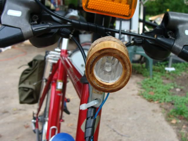
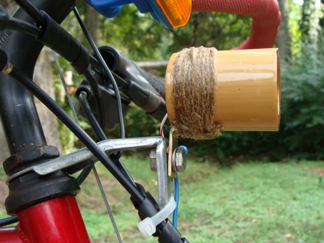
This one is made from Bamboo
Last edited by n4zou; 12-31-08 at 11:17 AM.
 02-21-08, 08:18 AM
#2
Reeks of aged cotton duck

Join Date: Oct 2007
Location: Middle Georgia, USA
Posts: 1,176
Bikes: 2008 Kogswell PR mkII, 1976 Raleigh Professional, 1996 Serotta Atlanta, 1984 Trek 520, 1979 Raleigh Comp GS
Mentioned: 0 Post(s)
Tagged: 0 Thread(s)
Quoted: 0 Post(s)
Likes: 0
Liked 5 Times
in
4 Posts
n4zou...
You da man! I love those things that make the bike useful for multiple purposes... and this application really makes a dynamo hub useful for something during those times when you don't need that headlight on.
Great job!
You da man! I love those things that make the bike useful for multiple purposes... and this application really makes a dynamo hub useful for something during those times when you don't need that headlight on.
Great job!
02-21-08, 09:30 AM
#3


Riding Heaven's Highways on the grand tour

Join Date: Aug 2006
Posts: 1,675
Mentioned: 1 Post(s)
Tagged: 0 Thread(s)
Quoted: 2 Post(s)
Likes: 0
Liked 3 Times
in
3 Posts
thanks!
Planning on ordering the LED and lense soon. This will give me a nice little project to work on for a weekend.
Planning on ordering the LED and lense soon. This will give me a nice little project to work on for a weekend.
__________________
1 bronze, 0 silver, 1 gold
1 bronze, 0 silver, 1 gold
02-21-08, 10:32 AM
#4
Scott
Thread Starter
Join Date: Jun 2006
Posts: 2,393
Bikes: Too Many
Mentioned: 0 Post(s)
Tagged: 0 Thread(s)
Quoted: 1 Post(s)
Likes: 0
Liked 1 Time
in
1 Post

10X30 lens and holder: https://www.luxeonstar.com/item.php?i...HS-HEB1-LL01-H

Heat sink, LED, and holder/lens fits perfectly in a 1" PVC pipe coupler from the hardware store for less than $1.

www.mouser.com has the diodes, capacitor, and terminal strips you need. Here is a photo of the 4 diodes soldered to a terminal strip attached to the front reflector mount and rack support.

Last edited by n4zou; 02-21-08 at 10:37 AM.
04-24-08, 09:16 AM
#5
Senior Member
Join Date: Oct 2007
Posts: 89
Mentioned: 0 Post(s)
Tagged: 0 Thread(s)
Quoted: 0 Post(s)
Likes: 0
Liked 1 Time
in
1 Post
Background: My power source is 12v dynamo + rectifier/smoothed + voltage regulator-> ~10.4v DC. I have a little box of electronics that has a voltage meter (for fun) and a voltage regulator that outputs 5v for USB devices and my 1W LED headlight (ebay thing, it has a built in current regulator on the heatsink). The original 10.4v is also fed back to some rear LED lights I made. But as per your allusion, I can't run both rear and front lights in parallel. I assume it's some sort of gross impedance mismatch.
Q1). I don't know if there's a standard solution, but do you think if I made a 555 timer 'switching circuit' that switched between rear and front lights at an imperceptibly high rate, this would be be a 'good electronic engineering solution'? If I added an adjustable switching rate I could make it act as a flasher too.
Q2). I've never been sure exactly how to rate NiMH voltages, but under load they're usually about 1.2v (1.4v open circuit, fully charged), so do you find that 4.8v reliably drives USB devices? The iPod, for example, seems to be notoriously picky about the exact pin voltages.
Q3). Ignoring the voltage drop, is there any merit in adding a diode in series with the USB? I imagine most devices have their own protection built in.
I'm sure i have photos of it somewhere.
All the best,
AR.
04-24-08, 03:44 PM
#6
Scott
Thread Starter
Join Date: Jun 2006
Posts: 2,393
Bikes: Too Many
Mentioned: 0 Post(s)
Tagged: 0 Thread(s)
Quoted: 1 Post(s)
Likes: 0
Liked 1 Time
in
1 Post
I've been waiting for a post like this for a while. First, please accept my hearty congratulations. Let me say that I've built something similar for my bicycle trailer, but I've been wanting to ask the opinion of someone knowledgeable in this area.
Background: My power source is 12v dynamo + rectifier/smoothed + voltage regulator-> ~10.4v DC. I have a little box of electronics that has a voltage meter (for fun) and a voltage regulator that outputs 5v for USB devices and my 1W LED headlight (ebay thing, it has a built in current regulator on the heatsink). The original 10.4v is also fed back to some rear LED lights I made. But as per your allusion, I can't run both rear and front lights in parallel. I assume it's some sort of gross impedance mismatch.
Q1). I don't know if there's a standard solution, but do you think if I made a 555 timer 'switching circuit' that switched between rear and front lights at an imperceptibly high rate, this would be be a 'good electronic engineering solution'? If I added an adjustable switching rate I could make it act as a flasher too.
Q2). I've never been sure exactly how to rate NiMH voltages, but under load they're usually about 1.2v (1.4v open circuit, fully charged), so do you find that 4.8v reliably drives USB devices? The iPod, for example, seems to be notoriously picky about the exact pin voltages.
Q3). Ignoring the voltage drop, is there any merit in adding a diode in series with the USB? I imagine most devices have their own protection built in.
I'm sure i have photos of it somewhere.
All the best,
AR.
As for running a wired taillight, You can remove one of the diodes from the bridge rectifier and replace it with 15 SMD LED's. Another option is to use 4 5mm LED's hooked up as a bridge rectifier circuit and a resistor to control current found experimentally hooked to the AC output of the dynamo. This is all covered at this link.
https://pilom.com/BicycleElectronics/DynamoCircuits.htm
I separated my lighting circuit from the USB circuit so I could switch on the headlight and allow any USB device connected to the USB connector to remain connected as you can not power both lights and USB devices. There is simply not enough power to do both.
04-24-08, 10:20 PM
#7
Senior Member
Join Date: Oct 2007
Posts: 89
Mentioned: 0 Post(s)
Tagged: 0 Thread(s)
Quoted: 0 Post(s)
Likes: 0
Liked 1 Time
in
1 Post
Thanks for the reply, and the link - very interesting. I like the idea of using LEDs in the rectifier. Obviously I don't fully understand how dynamos work. Time to finally think about how they drive a current.
My obsession with voltage regulation stems from the rather restrictive specs of the front LED light I'm using, also the voltage meter I added requires a voltage within a meagre 0.5v tolerance. I wouldn't be surprised if they make it as friable as possible to sucker all the cheapskates like myself.
Given the current status of the light I'll probably just try the embarrassing 555 flasher circuit approach. I do have a left-over 6v dynamo, so I'll perhaps build your circuit or test those on that website.
Cheers.
AR.
01-07-11, 03:57 PM
#9
Junior Member

Join Date: Oct 2010
Posts: 11
Mentioned: 0 Post(s)
Tagged: 0 Thread(s)
Quoted: 0 Post(s)
Likes: 0
Liked 0 Times
in
0 Posts
I also want to know if the LED lasted all this time.
I don't want to sound harsh but the design is a little crude.
The dynamo does not provide constant current neither constant voltage.
I think that the 6VAC that is written on the dynamo is the RMS value under a certain load with a certain speed.
That means that the voltage across the LED won't be 6V.
But after the full wave bridge (diodes) the DC output will be 6V*(square root of 2).
Even that I said is not correct because the dynamo's voltage output is not sinusoidal.
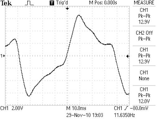
Only after a certain (high) speed it becomes a sinusoid. In my shimano hub dynamo the output is like that
As for the batteries, I don't think that NiMH batteries like being overcharged.
When the batteries are not full, the electrical energy you put into them, converts into chemical energy. When they are full, the electrical energy you feed them transforms into heat. Overheating is bad.
I must say that I am not 100% sure about the things I said above because it seems that your design works and the LED stayed alive. But I just can't accept it .
.
You see, I am also designing a circuit for the same purpose but with switching regulators for high efficiency and I am looking at other's circuits to steal some ideas.
I think that you(N4ZOU) made the PVC bike fenders. I tried making them a few days ago! They didn't turn out as nice as yours but they do their job.
I don't want to sound harsh but the design is a little crude.
The dynamo does not provide constant current neither constant voltage.
I think that the 6VAC that is written on the dynamo is the RMS value under a certain load with a certain speed.
That means that the voltage across the LED won't be 6V.
But after the full wave bridge (diodes) the DC output will be 6V*(square root of 2).
Even that I said is not correct because the dynamo's voltage output is not sinusoidal.
Only after a certain (high) speed it becomes a sinusoid. In my shimano hub dynamo the output is like that
As for the batteries, I don't think that NiMH batteries like being overcharged.
When the batteries are not full, the electrical energy you put into them, converts into chemical energy. When they are full, the electrical energy you feed them transforms into heat. Overheating is bad.
I must say that I am not 100% sure about the things I said above because it seems that your design works and the LED stayed alive. But I just can't accept it
.You see, I am also designing a circuit for the same purpose but with switching regulators for high efficiency and I am looking at other's circuits to steal some ideas.
I think that you(N4ZOU) made the PVC bike fenders. I tried making them a few days ago! They didn't turn out as nice as yours but they do their job.
01-07-11, 11:59 PM
#10
Senior Member
Join Date: Apr 2005
Posts: 912
Mentioned: 0 Post(s)
Tagged: 0 Thread(s)
Quoted: 34 Post(s)
Likes: 0
Liked 8 Times
in
7 Posts
I am an electrical engineer, and the circuit in n4zou's post scares me almost as much his explanation. Please don't try this at home! A dynamo is a current source, the voltage will vary with the RPM. Besides, as the batteries attempt to regulate the voltage they will be self-destructing.
01-08-11, 05:51 AM
#11
Junior Member
Join Date: Oct 2010
Posts: 11
Mentioned: 0 Post(s)
Tagged: 0 Thread(s)
Quoted: 0 Post(s)
Likes: 0
Liked 0 Times
in
0 Posts
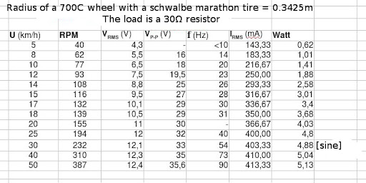
In case someone needs it, I made this table from my 3N72 hub dynamo.
It is some basic measurements to help me with my project.
I used a 30Ω resistor as a load.
Note that the RMS values are correct only after the speed of 30km/h.
My multimeter is only able to calculate the RMS values of a sine.
Before that speed, the output of the dynamo is not sinusoidal!
But you can get an idea of the output from the peak-to-peak voltage.
Also note that when there is no load the voltage of the dynamo can rise to 50Vp-p.
01-10-11, 09:58 AM
#12
Cottered Crank

Join Date: Aug 2010
Location: Chicago
Posts: 3,401
Bikes: 1954 Raleigh Sports 1974 Raleigh Competition 1969 Raleigh Twenty 1964 Raleigh LTD-3
Mentioned: 0 Post(s)
Tagged: 0 Thread(s)
Quoted: 8 Post(s)
Likes: 0
Liked 13 Times
in
8 Posts
I'm just an electrician and ham radio geek. The USB charging circuit looks a little fast and dirty to me too, but the LED side seems like it is a good start.
I'm putting a Nirve headlight on my Vintage Raleigh that is pretty nice looking from the outside but I wanted to re-wire and rebuild on the inside to be both a battery-powered smaller LED safety/marker light and also include a brighter LED powered by a bottle generator for more light when moving and still have that vintage 50's-70's feel.

I'd love to upgrade to a vintage dyno-hub but that's not in the cards right now unless one falls in my lap. I want to keep this bike as vintage-looking as possible and keep the bike from having too many visual modern anachronisms off of it but having a really BRIGHT LED hooked up to the bottle generator and installed into the headlight shell is not offensive at all to me.
I'm not sure if a 12v bottle generator is the way to go or stick with with 6v in the hopes I find a vintage S-A dynohub at some future date although I hear that they don't put out much output at all and many of them are ruined due to permanent magnet issues not being so permanent (especially if they have been disassembled incorrectly).
If any of the EE's in this thread have any bright ideas to improve this simple rectifier circuit I'd be all ears.
I'm putting a Nirve headlight on my Vintage Raleigh that is pretty nice looking from the outside but I wanted to re-wire and rebuild on the inside to be both a battery-powered smaller LED safety/marker light and also include a brighter LED powered by a bottle generator for more light when moving and still have that vintage 50's-70's feel.
I'd love to upgrade to a vintage dyno-hub but that's not in the cards right now unless one falls in my lap. I want to keep this bike as vintage-looking as possible and keep the bike from having too many visual modern anachronisms off of it but having a really BRIGHT LED hooked up to the bottle generator and installed into the headlight shell is not offensive at all to me.
I'm not sure if a 12v bottle generator is the way to go or stick with with 6v in the hopes I find a vintage S-A dynohub at some future date although I hear that they don't put out much output at all and many of them are ruined due to permanent magnet issues not being so permanent (especially if they have been disassembled incorrectly).
If any of the EE's in this thread have any bright ideas
to improve this simple rectifier circuit I'd be all ears.
01-10-11, 11:51 AM
#13
Junior Member
Join Date: Oct 2010
Posts: 11
Mentioned: 0 Post(s)
Tagged: 0 Thread(s)
Quoted: 0 Post(s)
Likes: 0
Liked 0 Times
in
0 Posts
I think that you can make a great, easy and highly efficient circuit that will drive the led but without a battery. You can add a battery, you can do everything with electronics but I am not 100% sure how. Without a battery, you can rectify the AC output of the dynamo with a full wave Schottky diode bridge, smooth it with a big capacitor, feed that to a switching voltage regulator (I will use the MAX5035 for its high efficiency) and by now you will have a constant voltage. Now you can use a LED driver to drive a high power white LED with the desired current. I am sure that, driving the LED with a current regulator will greatly prolong its lifetime. I will use the LM3405 to drive a CREE XP-G R5.
Note that this maybe a little expensive, the voltage regulator costs 10-12$ and a LED like the XP-G will not be cheap. But it's the best way I can think of to use a LED properly.
Note that this maybe a little expensive, the voltage regulator costs 10-12$ and a LED like the XP-G will not be cheap. But it's the best way I can think of to use a LED properly.
01-10-11, 12:01 PM
#14
Cottered Crank
Join Date: Aug 2010
Location: Chicago
Posts: 3,401
Bikes: 1954 Raleigh Sports 1974 Raleigh Competition 1969 Raleigh Twenty 1964 Raleigh LTD-3
Mentioned: 0 Post(s)
Tagged: 0 Thread(s)
Quoted: 8 Post(s)
Likes: 0
Liked 13 Times
in
8 Posts
I had planned on using the existing battery holder and circuit to power a small LED light at the top. I'd separately hook up a larger LED lamp at the lower position through a home-made bridge rectifier circuit with a capacitor to smooth it out and powered by the dynamo. I'd probably remove the original switch and replace it with a better one (I hear the one that comes on this headlight is pretty low-end) and only use it to switch the battery light on top -I might even keep it as a 3-position switch if I make another flasher board to flash the 9v battery LED.
The Dyno-powered bottom LED can simply be switched by snapping the dynamo to the off position. That's all the switch that circuit needs as if it needs to be off there is no point paying the drag penalty to have it against the tire.
I was thinking of using cheaper off-the shelf LED's. I don't want to spend a ton on this set-up.
01-24-11, 07:50 AM
#15
Junior Member
Join Date: Jan 2011
Posts: 5
Mentioned: 0 Post(s)
Tagged: 0 Thread(s)
Quoted: 0 Post(s)
Likes: 0
Liked 0 Times
in
0 Posts
I agree with you, don't try this at home. I'm not an electrical engineer, I just build stuff. I can tell you from my own personal experience that a SON Dynohub connected to a bridge rectifier and 4 AA nimh batteries will not regulate the voltage to 5.2 volts. When the batteries are fully discharged, the voltage from the hub is limited to 8 volts, too much for a usb device. As an added bonus, the batteries will overheat when charged at this rate.

Thread
Thread Starter
Forum
Replies
Last Post
rhm
Electronics, Lighting, & Gadgets
8
11-26-15 08:57 AM
Mock602
Electronics, Lighting, & Gadgets
11
09-23-15 05:10 AM
JoeSoMD
Electronics, Lighting, & Gadgets
3
12-11-09 08:21 PM
