Ok let us begin, chain suck is a problem where the chain grows through it's travel, this causes tension and it can be pulled, this forces pedal feed back through the cranks, this can be imprved by having a pivot design that pivots around the BB.
Now brake jack is a much more complicated thing. I am going to copy a post from another website, it is very VERY long so bare with me. It was written by uni student and is a 'basic' model and also discusses the pro's and cons of designing a bike so that it squats or jacks under braking.
Warning: very, very long posts.
Since there�s been a lot of incorrect explanations and theories on brake induced suspension interference (BISI), here�s a full explanation with diagrams. If you�re just interested in what happens but not so much �why� then skip to the end, most of this is just a reiteration of commonly-understood physics and its application to bicycles in relation to braking.
Disclaimer: this article is purely intended for demonstration of the basic concepts of BISI. It is not a full quantitative method of calculation, nor should it be used as such. Calculations shown deliberately omit various less-significant/more complex factors such as moments of inertia, weight shift, centres of mass etc. The article remains a fair approximation of the basics of BISI, but if you wish to calculate the precise reaction to braking that your bicycle has then you must be aware of the other factors, and know how to incorporate them. Keep in mind too, that motion characteristic generation (ie designing for a characteristic) is much more difficult than simply analysing an existing system.
The physics:
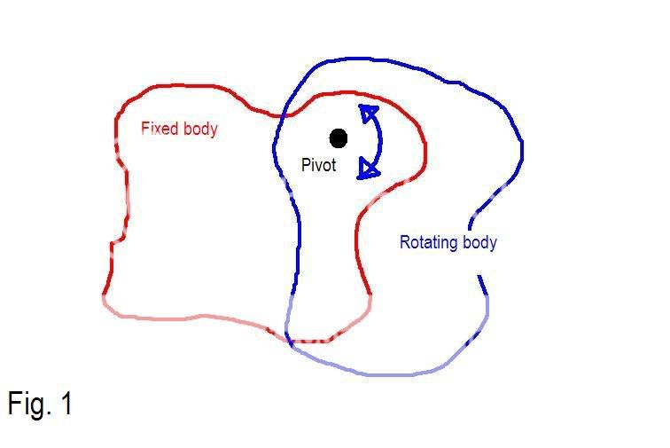
Imagine you have a random rigid structure/body attached to another, fixed rigid structure/body by means of a simple pivot, so that when the fixed (stationary) body is taken as a point of reference, the other one is free to rotate around the pivot that joins them. (Fig 1)
Now imagine if you had the same thing, but you applied a force at any random point on the rotating body. The force can be broken up into its vector components relative to the pivot, which are called the normal (directly towards/away from the pivot) and tangential (perpendicular to the normal) components, as shown. (Fig 2)
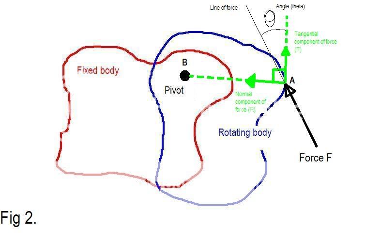
The concept of a moment is fairly basic � it is the product of a force and its perpendicular distance from another reaction force (which prevents the body from translating, ie moving in a straight line) at a fixed point (in this case the pivot), and measures their coupled tendency to cause a body to rotate. In other words, the tangential component of force F in figure 2 (since it is perpendicular to the normal force at point A), multiplied by the distance between point A and point B (the pivot), gives the moment acting on the rotating body, about point B. The tangential component of force is given by F x cos(q). So the moment about point B is Fcos(q) x dist(AB). Not too complicated. This is pretty easy to visualise � imagine lifting your front wheel off the ground (brakes not being applied) and pushing against the tyre with your hand. If you push directly in at the axle (perpendicular to the tyre/rim at that point; this is a purely �normal� force) then the wheel will not spin, and you will cause an equal and opposite reaction force on the wheel from the axle. However, if you push parallel to the tyre�s surface at that point (tangent to its path) then you will cause the wheel to spin. Anywhere in between will give a combination of the two � pretty obvious.
Newton�s second law of motion: SF = m x Sa
(the �S� means �sum of�, or �net�). That is to say, if there is a net force (that is not zero), there will be a net acceleration (in the same direction as the force is acting, obviously), directly proportional to the force applied and inversely proportional to the mass (due to the mass�s inertia resisting movement). The same applies to moments � the sum of all moments is equal to the body�s mass moment of inertia (the rotational equivalent of normal inertia) multiplied by the angular (rotational) acceleration. For the moment (no pun intended) you only need to understand the basic concept of this, not the technicalities (which are fairly complex).
Newton�s third law: For every action (force) there is an equal and opposite reaction (force). This gives us the concept of static equilibrium � if a body is supported in such a way that it cannot move (relative to your reference frame) then any force acting on it will generate reaction forces at its supports. Depending on the supports holding a body, it will be considered either statically determinate or statically indeterminate. If the body is statically determinate you can work out reaction forces based on basic equilibrium equations (forces acting in the X direction, forces in the Y direction, and moments about any given point), in other words it�s fairly simple to deal with. If the body is statically indeterminate, you will burn it at the stake and write several books specifically concentrating on denying that it ever existed (it�s much easier than doing the calculations). Fortunately, bicycle suspension components are (in the plane which they are intended to move, ie discounting lateral flex etc) nearly always statically determinate (and those which technically are not, can be approximated as being determinate anyway). If this sounds complicated, that�s because you�re not reading my mind well enough.
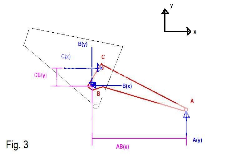
First we will look at a basic bicycle (single pivot) swingarm, (initially) having three points of attachment to the outside world. These points are point A (the axle), point B (the pivot), and point C (the shock mount). Note specifically that all three points are pivots and are free to rotate relative to the bodies to which they are attached (the front triangle, the shock, and the wheel). If you�re wondering why the axle is a pivot, it�s because the rear wheel is attached via bearings, and cannot exert a moment on the axle itself (because if you spin the wheel, it will simply rotate freely around the axle � leaving braking forces and chain interference out of the picture, and assuming that there is negligible friction in the wheel bearings). So the wheel and the swingarm can rotate independently of each other at this time. Assume the bicycle is on flat ground.
At sag, when the suspension is not cycling (moving), the bike�s swingarm is in a state of static equilibrium (all forces and moments sum to zero). See fig 3 � blue lines are forces acting at the various points, pink lines and letters are to show the notation used for the distances from C to B (vertically), and A to B (horizontally). Note that the force at A (the axle) can ONLY be vertical because any non-vertical (ie tangential) force at the tyre will simply rotate the wheel around the axle, transferring no force to the axle other than the vertical (normal) component. Also note that the force at C is only horizontal (axial to the shock) as shocks can only transfer load ALONG their axis (quite obviously � any force on the shock that is not along its axis will simply rotate it about its other mounting point). For ease of calculation, we will neglect the shock�s rotation relative to the front triangle, and assume it stays horizontal at all times.
Ok, so now into some basic calculations. Assume that A(y) is a given force on the axle. Since the swingarm is in equilibrium, moments about ANY point on the swingarm must sum to zero. For ease of calculation we will start with point B. Positive moments are taken to be clockwise:
SM(B) = 0
= [A(y) * -AB(x)] + [C(x) * CB(y)] Note that AB(x) has a negative sign in front of it
[A(y) * -AB(x)] + [C(x) * CB(y)] = 0
[A(y) * AB(x)] = [C(x) * CB(y)]
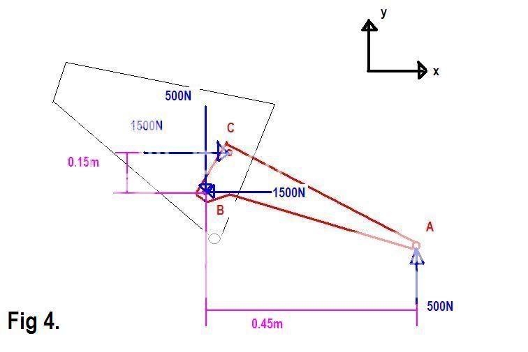
If we let AB(x) = 0.45 metres (realistic measurement), A(y) = 500N (again not unrealistic, this is equivalent to about 50kg), and CB(y) = 0.15 metres (we will assume that this distance does not change significantly over the stroke of the suspension, for ease of calculation), then we get:
[500 * 0.45] = [C(x) * 0.15] Divide both sides by 0.15 to calculate C(x)
[500 * 0.45]/0.15 = C(x)
C(x) = 1500N (this is roughly equivalent to 330lb � if you had a 330lb/inch spring you would get 1 inch shock stroke sag, which given the 3:1 shock leverage ratio would be 3� of sag at the axle � again, a realistic example).
So now we have calculated C(x) using basic equilibrium formulae. The only unknowns left are B(x) and B(y). Note that in Fig. 3 these forces are drawn in the opposite directions to C(x) and A(y) respectively. To calculate these we have two choices � balancing moments about either A or C, or balancing forces in the X and Y directions. Balancing the forces is easier since in this example all the forces are either horizontal or vertical, and we have no measurements for some of the distances necessary to sum moments about A or C.
SF(x) = 0
= C(x) � B(x) Minus B(x) because it is acting in the negative direction
\ C(x) = B(x)
B(x) = C(x) = 1500N
SF(y) = 0
= A(y) � B(y)
\ A(y) = B(y) = 500N
Hence we now have the reaction forces (Fig. 4)
Now consider a free body diagram of a wheel with a disc brake rotor attached, under braking forces. Assume the caliper is directly above the axle for ease of calculation. (Fig. 5)
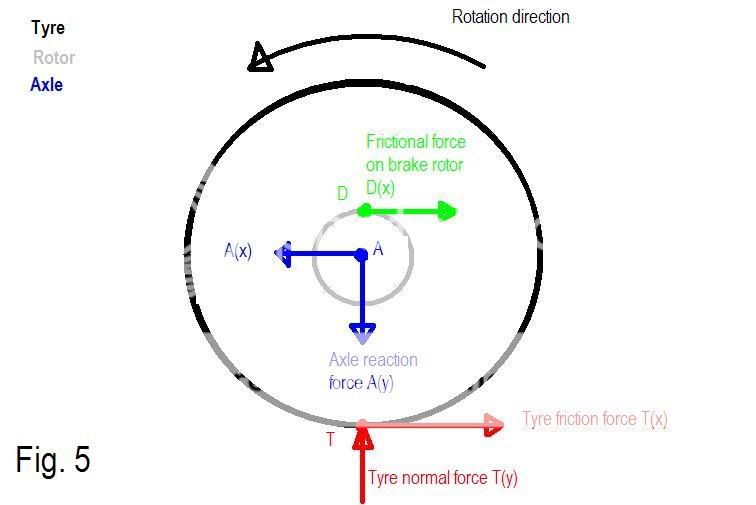
Assume that the bike, despite braking, is maintaining a constant speed (as though it�s rolling down a hill with the brakes applied to a level where constant speed is held). Due to the wheel�s axisymmetric structure (it is identical all the way around, ie everything is concentric about the axle � brake rotor, rim/tyre etc), if we are to neglect the wheel�s own rotational momentum (because relative to the other forces/momentums at play, it can be considered insignificant) then the wheel can be modeled as though it is in static equilibrium (since we�re not worried about loads internal to the wheel, only the external forces and reactions) � all (external) forces and moments sum to zero. Assume the radius of the whole wheel (to the outside of the tyre) is 0.33m (13�) and the radius of the disc rotor is 100mm (4�). Let us choose an arbitrary force for T(x), which we will say is 200N. Take positive rotation to be clockwise.
Thus:
SM(A) = 0 summing moments about the axle
= [T(x) * -0.33] + [D(x) * 0.1]
= [200 * -0.33] + [D(x) * 0.1]
200 * 0.33 = D(x) * 0.1
\ D(x) = 660N
SF(x) = 0
= D(x) + T(x) � A(x)
= 660 + 200 � A(x)
\ A(x) = 860N (pointing to the left in the diagram)
SF(y) = 0
= T(y) � A(y)
\ A(y) = T(y)
If we take axle force to be 500N once again, then
A(y) = T(y) = 500N
Now we will look at the reaction forces acting on the swingarm. Note that the forces are identical in magnitude at all points of attachment/contact with the wheel (that is, the axle and the caliper) but act on the swingarm in the opposite direction to the directions they act on the wheel (Newton�s action/reaction pairs). (Fig. 6)
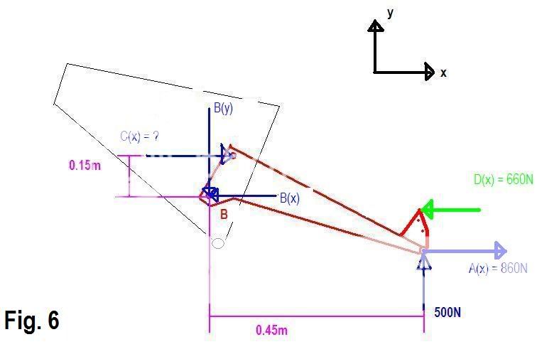
Note that the force acting horizontally on the axle (with regards to the frame, not the wheel) is the sum of the frictional force on the tyre, and the frictional force on the brake rotor, and that it is always higher in magnitude than the braking frictional force between the caliper/rotor � if it wasn�t, braking would actually accelerate the bike forwards due to a net forwards force acting on it (which obviously is impossible).
From here we have two options to analyse the effect of this braking force on the swingarm. Firstly and most obviously, we can simply use each point force (X and Y components acting on the axle, and the X component on the brake caliper) and their respective normal distances from the main pivot (at B) to calculate the moment about B and thus the reaction force C(x) (as well as the reactions B(x) and B(y) if we so desire). If the reaction force C(x) increases, then that means that the shock�s resistance/spring force has to increase (and the opposite is obviously also true). Given the nature of springs, we know that to increase the shock�s reaction force, it has to sit further into its stroke in order to compress the spring to suit.
The second method, and one which will prove more useful later on when considering linkage bikes/floating brakes, is to consider the forces acting on the swingarm from the caliper and the axle as a single couple moment (generated by the caliper force pushing forwards, and an equal force pushing backwards at the axle so as to have no net force in any direction) plus a horizontal force at the axle instead of two separate forces. In the diagrams shown, this couple moment would be anti-clockwise. This method has the advantage of being able to separate these two components so that we can recognise the following things:
- Regardless of the orientation of the caliper or its distance from the axle, the couple moment will remain the same for any given frictional force on the tyre; this is because that frictional force multiplied by the radius of the wheel is what gives the magnitude of the moment and it is independent of rotor size (note though that the caliper/axle forces change inversely proportional to rotor radius however).
- There are two elements which can semi-independently cause BISI, and thus are separable: these are axle path/horizontal axle force and the couple moment. Couple moments can easily be removed from the equation of by parallel linkages (including floating brakes) which will be covered later, and the horizontal force acting on the axle needs a moment arm (perpendicular to the line of force, so in other words a vertical distance) between the axle and the swingarm pivot, in order to generate a moment about the pivot. As such, both factors need to be taken into account when considering brake interference. It is possible (but not necessarily desirable) to create a setup where these two factors cancel each other out (this will be elaborated on later).
- What determines the amount of squat (or jack, but that will be dealt with later) is determined by two things: the height of the pivot (or instant centre, explanation of instant centre to follow shortly), and the length of the swingarm. The height of the pivot/IC is what determines the vertical distance (which is the moment arm as mentioned before) between the pivot and the axle, and so a higher pivot = longer moment arm = more squat generated by horizontal axle forces. The length of the swingarm changes the effects of the couple moment (which is effectively a constant for whatever calculation you�re doing) by altering the moments generated by the vertical force on the axle and the force of the shock on the swingarm, about the main pivot. For example, if, as above, the axle was 0.45m from the main pivot and the vertical force on the axle was 500N, the moment generated by that (which has to be equaled by the shock�s force multiplied by its normal distance [0.15m] from the pivot) would be 225N.m. A couple moment of say 22.5N.m would be an increase of 10% in this case, which if the shock rate was perfectly linear, would make the bike sit 10% further into its travel in order to regain equilibrium. Now consider that the swingarm was twice the size in every dimension; ie axle to pivot is 0.9m, and pivot to shock mount is 0.3m. The shock ratio is still the same so the shock doesn�t have to supply any additional force at equilibrium. However, the moments (note that these are not �net� moments and as such we are not concerned with acceleration) are now doubled also due to the doubled moment arms � that is to say, the axle force/swingarm length would yield a moment of (0.9 * 500 = 450N.m) that the shock would obviously balance out in the opposite direction. However, an addition of the 22.5N.m couple moment via braking is only a 5% increase now, half of what it was before. From this we can see that swingarm length is inversely proportional to squat generated by the couple moment alone.