Okay, so long story short I’ve had “the itch” for a while to build myself an e-bike that fits the following criteria:
1. ----- Fits on a bus bike rack without any issues beyond that of a regular bike.
2. ----- Can be loaded down with cargo with cargo racks in both front and rear and can haul a lot of stuff. We are talking Costco runs without a trailer loads usually only possible with a dedicated cargo bike usually with a long wheelbase that won’t fit on a bike bus rack.
3. ----- Has a 60-degree seat to BB angle so that I can easily put a foot down at a stop without having to slip forward off of the seated position for my foot to reach the ground while maintaining an upright riding position to maintain visibility both to see and to be seen.
4. ----- Uses a quiet efficient direct drive brushless hub motor mounted up in the frame driving through the bikes gears like a stoker-monkey set-up. I have a cyclone mid-drive set-up and the noise is annoying but a quite direct drive hub-motor in the wheel doesn’t have the low end tongue for hauling cargo or climbing hills. In frame hub-motor driving through the gears is the only set-up I know of that combines the best of both worlds.
5. ----- Uses a jack-shaft with dual freewheels to combine the motor and pedal input so that the pedals are not driven like an actual stoker-monkey set-up.
6. ----- A standard 7 or 8 speed spool of gears with standard 3/16” width chain with a derailer on the rear. Minimum double possibly triple chain-wheels up front one large one for free running and smaller one(s) for cargo hauling.
7. ----- Rear drop-outs should be forward hooked horizontal drop-outs to accommodate a forward up-angled rear derailer in a protective cage to keep it high and tight to prevent it being damaged or bent inwards in an act of vandalistic sabotage to grab the wheel spokes when shifting into low gear.
8. ----- The additional weight of the battery pack and hub-motor in the frame should be kept as low as possible and as forward as possible for stability both on the road and in a bike rack on a bus.
9. ----- Minimum 36V 20Ah battery capacity with the pack being constructed of high quality modular replaceable LiFePO4 prismatic cells.
10. ----- Sturdy double kick-stand that does not get in the way.
So far after a whole lot of fiddling around in CAD this is what I have come up with so far:
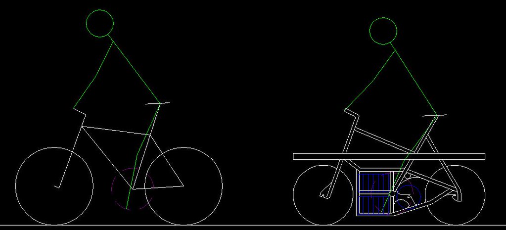
The specifications and geometry of my current “bus bike” and myself are represented in the left side figure. A fairly common 26” wheel bike set-up with a wheel base that is slightly longer then 43 inches and fits on a bus rack just fine but cargo carrying is limited to a rear rack, front & rear panniers, and back-pack where the size of the rear panniers are limited due to heal strike issues and the front panniers cannot be too heavily loaded without severally effecting steering stability. In addition as you can see the represented green stick figure which represents my body proportions cannot put a foot down on the ground at a stop without slipping forward off of the seat.
On the right is what I have come up with so far.
Wheel base is 44” in length with smaller 20” wheels being used. Front fork geometry is more stable for more weight carrying capacity up front without effecting steering a large portion of which can be loaded on the over the wheel front cargo rack formed by a continuous large diameter tube running the full length of the bike and front wheel panniers in most cases will be unnecessary. The same full length large diameter tube that is the spine of the bike forms a generous rear rack as well and large rear panniers or rear basket racks may be attached without heal strike interference issues since the bottom bracket has been moved forward which also provides the ability to easily put a foot down at a stop while remaining seated.
In blue color are the battery pack cells and the hub motor mounted in the frame behind the bottom bracket and forward of the rear wheel. The battery cells represented are high quality third generation LFP-G20 prismatic cells which are 20Ah capacity 3.2V LiFePO4 cells that I can pick up for $31 each plus shipping. They are 2.8” wide which should fit in single file within the frame width, 1.7” thick, and 6” tall not including their screw terminals on the top which should fit as shown in an in-frame double-decker rack forward of the bottom bracket with their weight down low, tight, and forward while still leaving me enough room to mount the motor controller circuit above them but still protected below the main spine beam of the frame.
The gearing jack-shaft would be mounted high above the hub-motor further up the seat-post tube from the bottom bracket so as to accommodate a rear derailer that is tucked up tight and high protected by the right side bottom chain stay which slant downward to connect with the bottom of the battery box built into the frame.
This is basically how the chain lines are worked out with the jack-shaft:
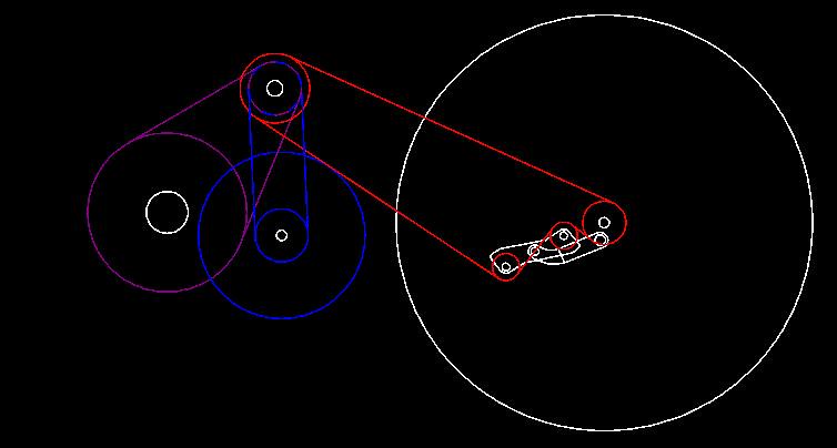
It’s color coded. The light purple colored sprockets and chain lines are from the bottom bracket and pedals up to the jack shaft, a 48 tooth chain wheel turning a 16 tooth single speed freewheel on the right side of the jack shaft. The blue colored sprockets and chain lines are from the frame mounted hub-motor up the jack shaft. A 16 tooth sprocket is attached to the left side of the hub motor represented by the large blue circle via. the six bolt attachment made for a disk brake. This part is available off the shelf as an after market conversion part and is made for people who want a rear flip-wheel on their bikes with one side being a fixy (the sprocket attached to the disk brake mount spot) and a single speed freewheel on the other side for a bike that can be either a single speed or a fixy by just flipping the rear wheel around a process easily accomplished in about 30 seconds with a quick release on the rear. A chain runs up from such a sprocket attacked to the left side of the hub-motor to a left side 16 tooth single speed BMX freewheel on the left side of the jack shaft and thus the jack-shaft can be turned by either the pedals. or the hub-motor, or both. A set of fixed output sprockets are then attacked to the jack-shaft which serve as the main chain-rings for the main chain running back to the rear wheel represented in red with the 7 or 8 speed rear spool and derailer on that rear wheel so that all gears are available to the motor and pedals concurrently. Using a 21 tooth output sprocket on the stub-shaft with 16 tooth input freewheels will increase the gear ratio step-up to 20” rear wheel such that the gear steps are the same as if the bike used the larger 26” wheel size with a 48 tooth front chain-ring. So a 21 tooth would be the large output sprocket on the jack shaft and lower gearing would be accomplished with smaller output sprockets. I would probably put a 15 tooth, an 18 tooth, and a 21 tooth output sprocket on the stub-shaft and rig up a front derailer to move the chain in-between them just like a regular front triple chain ring set-up.
A double kick stand will be mounted to the front of the battery rack part of the frame at the bottom where there is some clearance and will flip forward and up 200+ degrees.
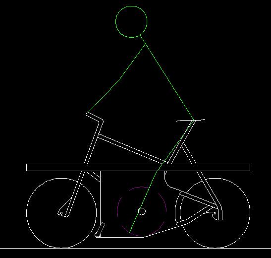
Also, both sides of the center section of the frame that houses the battery pack, hub-motor, motor control electronics, and jack shaft and gearing components to be covered by removable locking sheet metal covers to prevent vandalism or theft of those components. Basically keeping everything nicely boxed up in the frame and covered over on both sides with just the cranks with pedals showing on each side.
Here is another diagram showing the slabbed over with sheet-metal sides and the kick-stand in place in the folded up position (slightly darker grey color just behind front wheel):
Anyway, thought I would throw out what I’m trying to do and what I’ve got so far on this forum and see if any of you could point out anything I might have overlooked or anything like that.