Originally Posted by
cyccommute
“4 times“ what additional load? 4 times over the load of a rim brake which you’ve said doesn’t exist?
You are mixing up radial and torque loads caused by the braking force.
(
edit: after thinking more, disc brakes don't create radial loads on the axle, so no radial loads get transmitted to the spokes)
Rim brake force transferred to the spokes: Radial load only
Disc brake force transferred to the spokes:
Approximately 2.5 times the radial load, plus a torque load
Radial load from the rim brake force is perpendicular to the axle. (
edit: radial load on the axle will be approximately 2 times the rim brake force, if ignoring the effect of the tire diameter)
This in turn becomes approximately 2.5 times the radial load on the axle for disc brake wheels than rim brake wheels, which gets transmitted only to the spokes behind the axle that are exiting in the opposite direction of the radial load (this is because the radial load on the axle is the sum of the braking force plus the road friction, as shown in the see-saw diagram). (For a rim brake) The (key) spoke that eventually moves directly behind the axle perpendicularly to the radial load gets the most amount of this load, and the adjacent spokes pick up less of it for each consecutive spoke further from this first (key) spoke until you reach 0 load at 90 degrees. To make the calculations simpler I disregard the differences in distribution of the radial load among the adjacent spokes to the key spoke, and assume that the maximum load on that first (key) spoke will be the same as the radial load divided equally between 12 spokes (I initially thought 4 spokes, then 6 spokes, but 12 spokes seem to be more correct when you look at this wheel simulator which shows around +4kgf for the key spoke on an example 32 spoke rim with an 80kgf radial load on the axle
https://bicyclewheel.info/wheel-simulator/).
This radial load is affected by the factors of the tire diameter, rim brake sidewall diameter,
and disc brake rotor diameter. If you have a larger disc rotor, the difference in radial load compared to rim brake wheels will decrease. So you'll have to make assumptions about the sizes (
I assume the 2 are equal). The radial load will also be affected by the angle of the fork to the ground, because the brake force is perpendicular to the fork, but for simplicity, I assume that the brake force is parallel to the ground.
Torque load from the brake force to the spokes only occurs if the 2 bodies where the 2 ends of the spokes (hub flange and rim) have force applied tangentially in opposite directions around the center of rotation (axle). With a rim brake wheel, brake force is applied to the rim to counter the road friction on the tire tread. The hub is free to rotate, therefore there is no torque load transmitted to the spokes (except for the insignificant amount of friction from the bearings in the hub).
Torque load from the brake force is transmitted to the trailing spokes with disc brakes, because the disc brakes are applying a tangential force to the hub flange, which is in the opposite direction to the tangential road friction on the tire/rim. Disc brakes will create somewhere around 3.5 to 4 times (
assume 4) the brake force than rim brakes because the disc brakes are 3.5 to 4 times closer to the axle than the rim brakes, in proportion to the radius of the tire (
assuming 160mm disc rotor and ISO 622mm rim, 32 spokes). Torque load will be applied to all trailing spokes (there are 16 on a 32 spoke wheel), but almost all will be to the trailing spokes on the disc side (there are 8 on a 32 spoke wheel, assume 90% load), and only some to the drive side (assume 10%). Torque load on the trailing spokes from the brake force will be a multiple of the proportion of the diameter of the disc rotor to the diameter of the effective hub flange spoke hole circle (which depends on the exit angle of the spokes, which needs a lot of assumptions for many factors). Because every wheel will have very different dimensions, I assume the disc brake pads are clamping at 150mm diameter on the rotor, and the effective hub flange spoke hole circle is 50mm. That makes the torque load from a disc brake transmitted to the trailing spokes a multiple of 150/50 = 3 times the disc brake force. So then if the disc brake force is 4 times the rim brake force, then torque load on the trailing spokes from disc brake force transmitted to all the trailing spokes will be 3 x 4 = 12 times the rim brake force.
Then you will have to divide the radial load and the torque load each separately among the affected spokes.
With my previous example of 370N rim brake force, assuming (
tire has no thickness and) the radial load is divided equally to 12 spokes (for simplicity), then a 6.3kgf from the radial load would be applied to the key spoke by the rim brake force.
A disc brake force producing an equivalent deceleration, with all the previous assumptions on sizes of components and 32 spokes, would produce a
15kgf (from radial load) + 51kgf (from torque load)
= 66kgf on the key trailing spoke on the disc side.
edit - with all the assumptions: F = rim brake force
rim brake key spoke load from rim brake force (radial load) = 2F/12 = 0.167F
disc brake spoke load from disc brake force (torque load) = 12F/8x0.9 = 1.35F
1.35/0.167 = 8.1
disc brake spoke load = 8.1 x rim brake key spoke load
edit of edit: https://www.sheldonbrown.com/torque-spoking.html
For disc brake torque, the sheldon brown article ignores the disc rotor diameter, and simply estimates the ratio of effective hub flange spoke hole circle diameter to be 1/12 of the rim diameter. I still got 12F with my assumptions, so the proportion is the same.
However, the sheldon brown article divides the torque load by all 32 spokes to calculate the increase in tension of the trailing spokes. I assumed 90% of the torque went to the 8 trailing spokes on the disc side. So my result of 51kgf would be (32/8x0.9) = 3.6 times greater than what the sheldon brown article came up with = 51/3.6 = 14.2kgf. That would be 14.2/6.3 = 2.3 times greater than the radial spoke load from rim brakes, compared to the 8.1 times that I came up with. I don't know which method is correct. For 120kgf pretension, the rim brake would add 5% extra load to the spokes, and disc brakes would add extra 12%.
This is only the braking force. This does not include the pretension of the spokes and the force of gravity on the mass of the bike and rider.
I've already admitted that I don't know how to correctly translate some of the forces and I've made a lot of assumptions, so the proportions and amounts that I've calculated could be very wrong. But I think 2 things are clear, even with the incorrect assumptions, which are: 1) disc brakes create more load on spokes than rim brakes do, and 2) rim brakes do not transmit torque to the spokes.
Originally Posted by
cyccommute
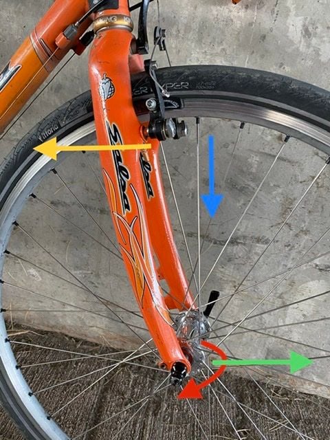
Rather than use a poor analogy, how about using the wheel. Consider the rim brake example below. The green arrow is the forward momentum of the bicycle acting through the hub. The yellow arrow is the braking force acting against the forward momentum. The red arrow is the rotation of the hub and the blue arrow is the action of the hub on a spoke. (Each spoke would have it’s own arrow.) During braking, the hub is pulling the spoke down in a circle. The spoke should continue in a straight line but the hub is pulling it in a circle. That’s torque, plain and simple.
The amount of force that is applied to the spoke is proportional to the force used to stop (or slow) the forward motion of the bike. The force is also limited to the force used to stop the bike. That force is the same independent of the type of brake used. Bicycles can’t develop much more than about 0.5g of deceleration. Multiply that times the mass of the rider/bike and you have the maximum force that can be applied.
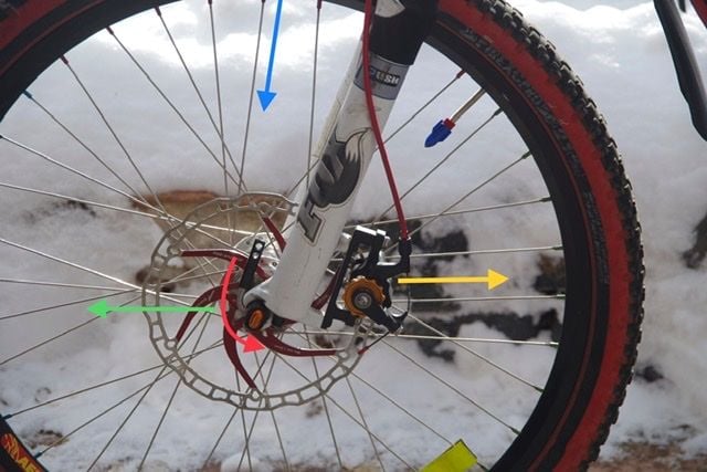
Now compare the above to a hub mounted disc. The same parameters...forward momentum, braking force and torque on the spokes... applies. I can’t see where there is any increase on the force on the spokes. The application of the force is in a different location but the forces work the same way. The hub is pulling the spokes around just like the hub in the rim brake example is.
You keep saying that a rim brake doesn’t impart torque onto the hub through the spokes but that simply isn’t true. The brakes don’t impart torque onto the axle but they most certainly impart torque onto the hub shell. The hub shell pulls on the spokes when the bike moves forward and the rim pulls on the spokes when the brakes are applied. If they didn’t impart torque onto the hub shell, the wheel would never stop.
Now the reason that I say there is little to no difference is because the only force that we can work with is the braking force. The braking force is the same in each system because the mass and acceleration is the same. If you are going to have 4 times as much stress on the spokes of the wheel, you have to have 4 times the braking force. Disc brakes don’t provide 4 times the deceleration of rim brakes.
Your force diagrams are very wrong. You are mixing the forces on the fork with the internal forces of the wheel. What we are discussing is the wheel as a closed system.