Here is the start of the new axle section.
Based off of a design that the guy I ran in to on the Ohio to Erie Trail run I did a few years ago that used an adjustable "outer rail" for the outside support of his wheel axles, I wanted to incorporate an "outer rail" in to my design also. However, his design used All Thread rod spanning the width of the trailer from outer rail to outer rail. Then he had several nuts that he could screw in and out to adjust for hub/axle width at the wheels. The reason he did this is he was using old 20" kids bike wheels and would make use of both the front and rear wheels. The fronts and rears have different hub/axle widths.
In my design, I am not using old/surplus/scrap bike wheels. I built a new set for this, specifically. However, my concern is replacement parts down the road.
At the moment the hubs I have are 100mm. That is a hair under 4". The widest hubs are about 142mm, or about 5.6". So I made the outer rail spacing 6" to have some range to work with.
The inside axle flanges will be welded to the inside "strut". The outer frame rail flange will be adjustable. That part I haven't figured out just yet. I will have a bit over 2" to need to span. What I do want to do is make it to where the flange bolts on underneath the outer rail. I intend to cut open the tubing in that area and weld in a thicker plate that I can drill and tap. If I drill and tap the tube wall there isn't much meat there to thread in to. So by replacing that with thicker metal there is more thread area. I've done that before on another project, though in that case I welded deformed thread (oval holes) lock nuts to the inside because I wanted better holding power than straight threads. In the case of the trailer here I think I'll be OK with straight threads and drilling/tapping a plate will be easier than trying to weld small nuts on.
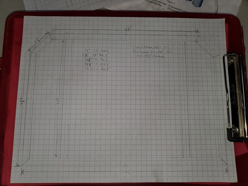
I don't have all the dimensions on this drawing for the wheels/hubs/axles etc, but the frame lines should give you an idea what I am going after.
The axles will sit in the middle of the areas where you would think wheels would go. There is 24" between the front and rear frame members, so the axles would be at the 12" point front to back. There is 6" between the struts and the outer rails and the fixed axle point is always inside. So the hubs will be centered closer to the insides. However, with the disk brake hubs the rims are offset from the hubs. I have an 11mm offset figured in right now. However, that may change. That 11mm shift would be where the rim is centered on the hub flanges - towards the outside (I have disk brake hubs and the brake mount is inside, so that pushes the inside flange to the outside - which is where that 11mm shift is).
Also not drawn/in the "put the idea down on paper" phase is the reason for the disk brake hubs. I want to build a dynamo/generator based off of a variant of Hugh Piggot's wind turbine idea. His uses a 3 phase stator. I am not sure what the designing will point me to, however I am wanting at least a 3 phase design with staged coils. That way - with coils of different intensities I can vary the output/drag. For example - if I am pedaling on flat ground or up hill I don't want a whole lot of drag so by using a light set of coils I can get some output. Or if I am cruising down a hill where I have all the weight and gravity getting me down I could switch in heavy coils (or all of them) and make use of that gravity. Or if I am stopping I can have the in-line coils staged based on brake actuation so I can make use of that momentum and the resistance of the electrical generation to slow me down. With one intensity of coil it is more difficult to do that, however you could use the idea of stacking the phases to do the same thing where one phase would be light, 2 phases would be medium, and all 3 phases (in a 3 phase design) would be heavy output/resistance. The down side to that is your bottom end/lightest intensity/lowest drag setting at 1 phase may still be too much for general pedaling on flat ground. Having a lighter option would give you some power where you may not have any otherwise. There again, when cruising down a hill it would make sense to take the most advantage of that as possible. If all the coils were light you're leaving a lot on the table. So being able to have heavy coils (and all of them stacked together) gives you that range. A balanced 3 phase stator isn't going to provide that range very well.
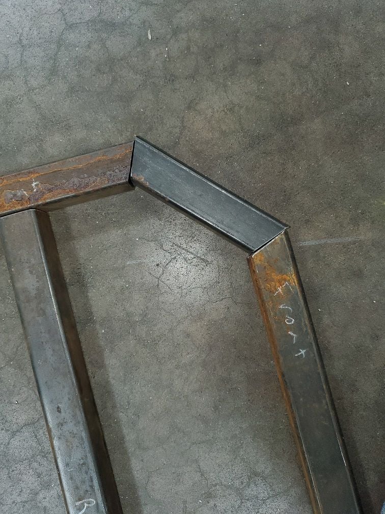
This is the raw layout of the cut and angled parts. The angled ones (all but the 2 inside struts) have angles. The bottom frame to side frames are 45deg's and the 45deg parts joining up with the side and front frames all have 22.5deg angles. Those parts I cut at a 1/8" longer dimension than what I measured off my drawing. That way I could tune the fit of the angles.
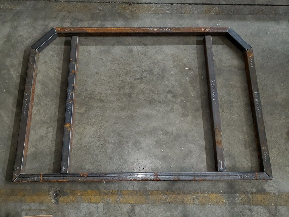
The first angles I tuned were the longer pieces. Then I went to the short 45deg pieces. This is the starting point. The goal is to get the parts to mesh with very little gap between them. If I cut them too big there would be a larger gap needing to be filled when welding. With the process I am running (stick), filler (stick electrode type/size), and base metal (relatively thin tubing) it is very difficult to span gaps - the arc will blow the edge away pretty quick. By having a tight fit there is less chance of the arc blowing through the edges.
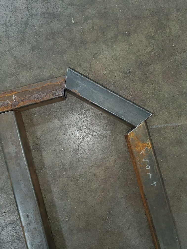
Getting closer...