


Suntour Ultra Conversion to 8-speed
 09-14-19, 10:39 PM
#51
Used to be Conspiratemus
Join Date: Jan 2009
Location: Hamilton ON Canada
Posts: 1,512
Mentioned: 4 Post(s)
Tagged: 0 Thread(s)
Quoted: 297 Post(s)
Liked 245 Times
in
163 Posts
Warning: a lot of detail here. I don’t want anyone to get hurt trying this at home. Those of you with real machine-shop skills and tools will probably give an eye-roll at my efforts but I learned a lot doing it and would like to share. Relating to OP @Eiko’s project, I believe he needs to place his fasteners farther out radially on the inner-most native freewheel sprocket – where they will foul the chain if even a little proud. And he is working with less clearance to the spokes than I have with my unusual hub. So if I understand correctly, he will need to set his fasteners perfectly flush with both sprockets, while I did not. He also has to get that grafted freewheel sprocket to pass over the obstructing freewheel body flange to overhang the hub. In my case the freewheel sprocket hole is much larger than the cassette body flange, so easy peasy. His project is inherently harder for that reason alone because he has to cut a big hole in a hard sprocket.
Selecting and making the fasteners was the hardest part for me. I considered using Rivnuts in the freewheel sprocket, as per @masi61, but this would have required my buying an expensive hand tool that I wouldn’t have much use for later. Nonetheless, the Rivnut idea of a long sleeve of female threading instead of just an ordinary nut would provide better support to the male threaded part. It pointed me to what are indeed called sleeve nuts, (aka Chicago screws or “sex-bolts” in the trade.) I wanted stainless steel because I figured I’d be having to cut the fasteners to fit and didn’t want cut edges to rust. And it looks nice.
**I have tried to respect convention about the difference between bolts and screws. Your water bottle cage is held on with machine screws going into bosses in the frame or by bolts going into nuts that hold frame clamps...but your C&V seat post is held by a binder bolt even though on many bikes, the part you turn is the male threaded part, not the nut…and the female threaded part might even be the frame itself, in which case the male part is surely a screw. So I’m not clear whether a screw being driven into a stationary sleeve nut (to make a “sex-bolt”) is in fact a bolt or a screw. However, when we buy a male-threaded fastener with specified threads and no unthreaded “dowel” portion, the package always calls them machine screws, not bolts. Bolts are on a different rack, with nuts nearby. So I am going to refer always to the male threaded part as a (machine) screw, not a bolt. I know getting this wrong annoys people who work with fasteners a lot and I’ll apologize if I’ve made an error here.
What I needed was something like this:
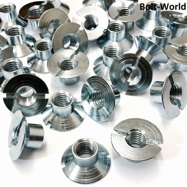
Sleeve nuts, zinc plated, from seller's listing
...but in stainless steel. Given the sprocket thickness of ~ 2 mm and the 3 mm space to the next sprocket, I needed the nuts to be 5 mm deep (plus an allowance for imperfect countersinking as described earlier.) 5 mm of thread would be just adequate for an M5 screw and ample for anything smaller.
Lots of people carry them, but hardly any will sell small retail quantities to individuals. Shout-out to Spaenaur Fasteners in Kitchener, Ontario, who will cheerfully let you come in to their family-owned warehouse and buy one screw, and they’ll even mail it to you (in Canada; for export, minimum order is $100)….but they didn’t have any stainless-steel sleeve nuts (almost everything else, though…) So I found these tamper-proof guys at Bolt World in the U.K.
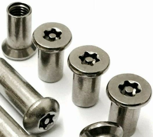
Tamper-proof sleeve nuts, stainless steel, from seller's listing
They are obviously too long (16 mm in fact) and not threaded to their head ends, but I thought I could drill and tap them the rest of the way through since I didn’t need the tamper-proof feature (obviously.)
I ordered a pack of 10 in M5, thinking at first I’d just use an M5 machine screw on the male side. The postage was almost as much as the price of the 10 nuts but they must have been on the next plane out of London because they got here in a couple of days. (They send the special Torx bit free with every order. Think of the tampering I can get up to now!) With the sprockets and fasteners in hand, though, I decided that 5 mm holes in the narrow web of the cassette sprocket would be too big; 4 mm was more appropriate. So after staring at the nuts for a while, and looking in catalogues at other varieties of sleeve nuts, I got this idea: I’d drill a smaller hole clear down through the solid head of the sleeve nut and tap it to take an SAE 8-32 screw. The question was: on shortening it to 5 mm (to fit the sprocket spacing,) would I have 8-32 threads through the entire 5 mm? or would some of that 5 mm be too-big, original M5 threads? Fortunately, measurement with a depth gauge showed the factory threading stopped 6-7 mm short of the head. So on cutting to 5 mm I would have 8-32 threads over the entire length, with some loss at the head end to the Torx recess. Being smaller diameter (about 4 mm), an 8-32 requires less thread length in the nut for proper mating than an M5 does. As a bonus, the sleeve would be thicker (and therefore stronger) than a sleeve nut originally made in 8-32 because it had started out with an outside diameter large enough (1/4”) to be drilled and tapped M5.
Essentially I was turning this:
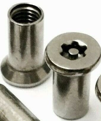
into this:
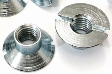
…but with a thicker sleeve and bigger head than these nuts would have if manufactured in 8-32.
Like this:
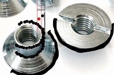
Sleeve nut on steroids. The red dot between the red lines shows the thickness of the sleeve of a open-end nut manufactured to 8-32. The black dots show the additional thickness of the sleeve of a blind-end M5 nut drilled out to 8-32 beyond where the factory threading ended. The head of the nut is also larger, as imagined by the crude black arcs. (The excess length consisting of the un-needed M5 threads is imagined to have been cut off.) *Cartoon does not purport to depict true-to-scale differences between actual 8-32 and M5 nuts.
In Canada, SAE taps and fasteners are more widely available with greater choice than metric, still. Also I suspected the project would destroy a tap and a drill bit – it did -- and I wanted to save my hard-to-find metric tools for projects where metric was essential to fit something else. 8-32 stainless oval-head machine screws were easy to find at Rona (now owned by Lowe’s.) I bought them over-long to avoid frustration later.
OK, to work:
Drilling and tapping stainless steel is hard to do well, much harder than drilling the holes in the sprockets turned out to be. I have one of those gadgets that work like a poor man’s drill press to help make straight holes. They are essential for installing locksets in doors where the holes have to be perfect or the lock will bind. Screwed to the bench it provided some much-needed support.
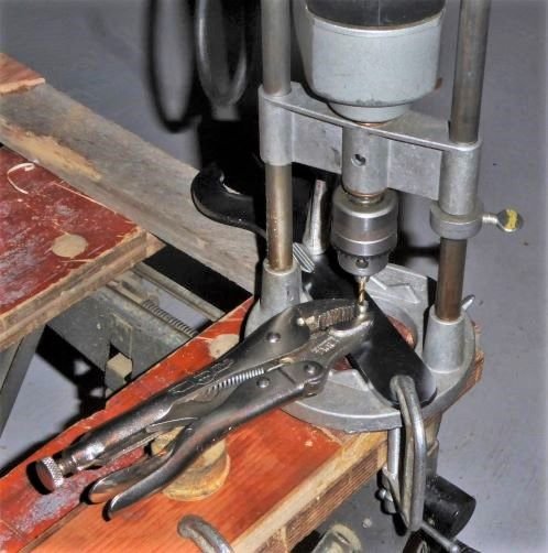
Post-production mock-up for photographs, not in real time. The workpiece shown has already been drilled and tapped. In use, my protected left hand would be holding the ViceGrips and my weight would be pressing down on the drill. The WorkMate has the legs retracted so I can get my upper body weight over top of the drill.
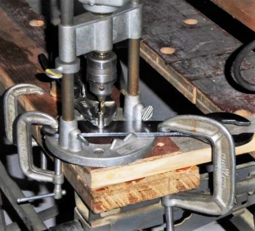
Clamped tightly. Anti-seize and oil would be close by in use.
Holding the workpiece steady was difficult but the kludges got the job done.
I had to drill straight down the existing hole into the solid part and then get through the broached head. Here the bit would jam as it broke through because the metal “anvil” (a headset wrench clamped to the apparatus) could not be put in contact with the bottom of the recessed hole. To save the specially sized tap drill, I drilled first with a slightly smaller cobalt bit and then followed through with the #29. Stainless steel work-hardens if drilled too fast and galls easily, so slow speed, heavy pressure, careful vertical alignment, and gobs of anti-seize with oil on the bit and down the hole. Withdraw the clockwise-spinning drill frequently during the cut to keep swarf from jamming the bit, and replenish anti-seize. (When drilling in a deep hole, the little curlicues of metal that come off don’t have any place to be evacuated to.) Even with the drill guide, it took some practice before I started getting adequate holes. The Torx broaching survived, even in my “seconds”, which confirmed my suspicion that the good threads do not include the Torx hole depth because otherwise the drilling and tapping would have obliterated the Torx marks.
Holding the sleeve nut in place while drilling it was also a challenge. I clamped the nut in ViceGrips as firmly as I dared, as close to the solid, undrilled end as possible, and planted it firmly and flatly on the “anvil” under the drill bit. I held the ViceGrips in my left hand with a Kevlar oyster-shucking glove in case anything broke. When the going gets tough, you have to watch (through your safety glasses) for the nut spinning in the ViceGrips and the drill bit spinning in the chuck. Breaking through was not easy, needed finesse that I started to acquire near the end. Something other than an anti-tamper Torx would have made breaking through easier, but I worked with what I had. I did break the #29 drill bit, fortunately after I had made 8.
Next was to tap the holes 8-32. I used the tap I had on hand, a TiNC-coated one from a set. According to the good people at Spaenaur, black oxide taps are better in stainless steel, which I will use if I ever do this again. Followed the standard rules for tapping but with anti-seize plus oil for lubrication. Extra careful to start straight down the hole as it is, even if the hole is not perfectly vertical, (two hands on the tap wrench), little clockwise bites and frequent reversing and full removal to clear swarf. Because the anti-seize is gooey, swarf doesn’t just drop out the bottom of the hole. Clamping in the vice was mostly sufficient to hold the work steady. If the nut turns in the vise, adjust tapping technique, don’t just tighten the vice. With patience, and care to get the tap started straight, 7 came out OK. On the next one, perhaps because I was tired, I broke the tap from not getting it straight and it seized up when it tried to cut out of the hole before I recognized what was happening. It was probably dull by then, too.
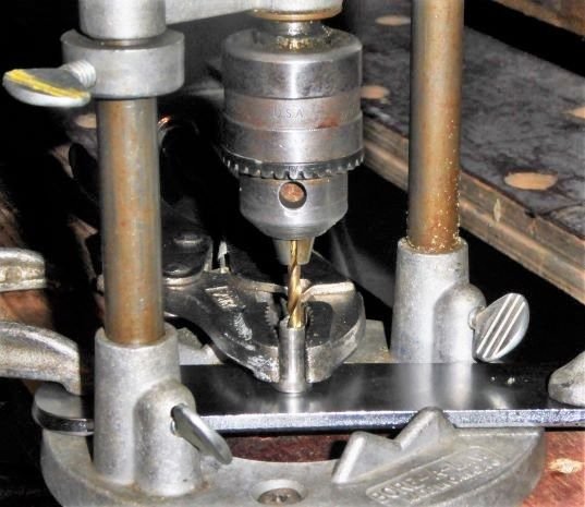
This photo shows what two looked like, after drilling and tapping.
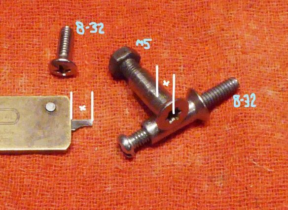
Through the mill. Checking for thread depth. x = 6.0 mm
The M5 hex-head screw has been turned in till it stopped at the end of the factory threads. The depth gauge “x” indicates the distance from the face of the head end through the 8-32 hole to the end of the hex screw, 6.0 mm in this specimen. The other sleeve has a common steel 8-32 machine screw passed all the way through, just to demonstrate that the threads are clear. In the upper left is one of the stainless steel 8-32 screws that will be used in the actual build.
On checking, they were all > 5 mm, confirming what I had predicted from measurements taken before drilling.
Hard part's done.
Even though a Torx bit will still engage the sleeve nut, it won’t be useful for assembly because as the screw approaches the open end it will push the bit out. Picking out the best six, I sawed and filed a slot in each one to accept a screwdriver, in whose blade I filed a “U” so the emerging screw would have room to clear – they are over-long remember. The slots show in photos on the previous post.
All these operations were done before cutting the sleeve nuts to the proper length. First, the more length there is to grab onto, the easier go the earlier steps. Second, I wouldn’t know exactly the correct length to cut them until I had test-fitted them through the holes in the freewheel sprocket….which I hadn’t drilled yet.
I outlined the drilling of the holes in the sprockets in the previous post. The sleeve nuts were �” outside diameter. After drilling with a black oxide �” bit, I chased it with a bit 1/64” larger to allow some slop for alignment error, because I knew the holes in the nuts weren’t perfectly vertical. (I filed a little relief into the holes in the Uniglide sprocket, too, for the same reason.) The valve-nut spacers needed to have their threads drilled out to fit over the �” sleeve nuts. Now, to cut the nuts to the right length, I inserted a sleeve nut into a countersunk hole and slipped a spacer on over it, then marked it to be just proud of the spacer -- don't want to throw away any hard-won threads. Clamping the nut sideways in my vice, I found that the notch cut into one jaw was just the right distance from the end of the jaw so that with the sleeve nut’s head nestled in the notch, the end of the jaw made a correct guide for the hacksaw. Sweet.
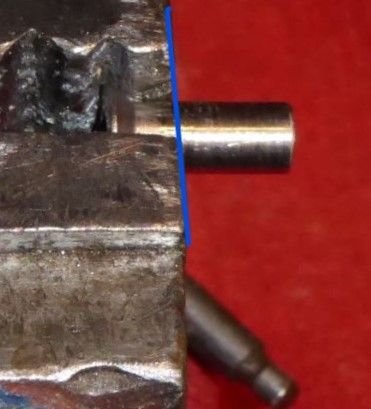
Sometimes you get lucky. Just saw here.
Cut to length, I re-inserted the nuts into the freewheel sprocket from below and slipped the spacers on from above. (I did not try to return each nut to the hole it was measured in. Bad me.) I clamped the sprocket to the workbench, trapping the sleeve nuts in place, and filed the top ends down until flush with the spacers. Careful, the stainless steel is harder than the cheap metal valve nuts so you get no “feel” that you’ve reached the stop. I then deburred the filed ends with a few spins of a countersink.
Are we there yet?
Now, before assembly, remember that the sleeve nuts have been drilled, tapped, sawn, and filed. Their threads are contaminated with swarf which will resist and gall anything stainless screwed into it. To get them as clean as possible, I sprayed WD-40 into them, ran a strip of rag through them, blew them dry, and then chased them with a plain steel machine screw (the one in the photo above, actually.) Then I reinserted them into the sprocket, slipped the spacers back on, now at last ready to accept the 8-32 screws.
I set the Uniglide sprocket on top of the spacers, checked that there was no rocking from high spots. Then I coated the machine screws generously with anti-seize and gently fed them into the sleeve nuts. They all went in without complaint. At first the sleeve nuts needed steadying with the cut-out screwdriver but as they nestled down into their countersunk holes, friction alone kept them from turning. Final torqueing was accomplished from the male side without any assistance, just like installing a chainring to a crank spider when it goes well. Oh yes!
Once satisfied they were all tight, I sawed off the protruding ends of the screws, filed the cut surfaces, and then went over the six of them with emery cloth to remove any rough edges.
With that, the completed double sprocket was ready to be installed with the cassette onto the freehub, as in the previous post.
Now I just want to enjoy riding my almost pro-looking 8-speed cassette. Thanks for watching! (as if...)
Selecting and making the fasteners was the hardest part for me. I considered using Rivnuts in the freewheel sprocket, as per @masi61, but this would have required my buying an expensive hand tool that I wouldn’t have much use for later. Nonetheless, the Rivnut idea of a long sleeve of female threading instead of just an ordinary nut would provide better support to the male threaded part. It pointed me to what are indeed called sleeve nuts, (aka Chicago screws or “sex-bolts” in the trade.) I wanted stainless steel because I figured I’d be having to cut the fasteners to fit and didn’t want cut edges to rust. And it looks nice.
**I have tried to respect convention about the difference between bolts and screws. Your water bottle cage is held on with machine screws going into bosses in the frame or by bolts going into nuts that hold frame clamps...but your C&V seat post is held by a binder bolt even though on many bikes, the part you turn is the male threaded part, not the nut…and the female threaded part might even be the frame itself, in which case the male part is surely a screw. So I’m not clear whether a screw being driven into a stationary sleeve nut (to make a “sex-bolt”) is in fact a bolt or a screw. However, when we buy a male-threaded fastener with specified threads and no unthreaded “dowel” portion, the package always calls them machine screws, not bolts. Bolts are on a different rack, with nuts nearby. So I am going to refer always to the male threaded part as a (machine) screw, not a bolt. I know getting this wrong annoys people who work with fasteners a lot and I’ll apologize if I’ve made an error here.
What I needed was something like this:
Sleeve nuts, zinc plated, from seller's listing
...but in stainless steel. Given the sprocket thickness of ~ 2 mm and the 3 mm space to the next sprocket, I needed the nuts to be 5 mm deep (plus an allowance for imperfect countersinking as described earlier.) 5 mm of thread would be just adequate for an M5 screw and ample for anything smaller.
Lots of people carry them, but hardly any will sell small retail quantities to individuals. Shout-out to Spaenaur Fasteners in Kitchener, Ontario, who will cheerfully let you come in to their family-owned warehouse and buy one screw, and they’ll even mail it to you (in Canada; for export, minimum order is $100)….but they didn’t have any stainless-steel sleeve nuts (almost everything else, though…) So I found these tamper-proof guys at Bolt World in the U.K.
Tamper-proof sleeve nuts, stainless steel, from seller's listing
They are obviously too long (16 mm in fact) and not threaded to their head ends, but I thought I could drill and tap them the rest of the way through since I didn’t need the tamper-proof feature (obviously.)
I ordered a pack of 10 in M5, thinking at first I’d just use an M5 machine screw on the male side. The postage was almost as much as the price of the 10 nuts but they must have been on the next plane out of London because they got here in a couple of days. (They send the special Torx bit free with every order. Think of the tampering I can get up to now!) With the sprockets and fasteners in hand, though, I decided that 5 mm holes in the narrow web of the cassette sprocket would be too big; 4 mm was more appropriate. So after staring at the nuts for a while, and looking in catalogues at other varieties of sleeve nuts, I got this idea: I’d drill a smaller hole clear down through the solid head of the sleeve nut and tap it to take an SAE 8-32 screw. The question was: on shortening it to 5 mm (to fit the sprocket spacing,) would I have 8-32 threads through the entire 5 mm? or would some of that 5 mm be too-big, original M5 threads? Fortunately, measurement with a depth gauge showed the factory threading stopped 6-7 mm short of the head. So on cutting to 5 mm I would have 8-32 threads over the entire length, with some loss at the head end to the Torx recess. Being smaller diameter (about 4 mm), an 8-32 requires less thread length in the nut for proper mating than an M5 does. As a bonus, the sleeve would be thicker (and therefore stronger) than a sleeve nut originally made in 8-32 because it had started out with an outside diameter large enough (1/4”) to be drilled and tapped M5.
Essentially I was turning this:
into this:
…but with a thicker sleeve and bigger head than these nuts would have if manufactured in 8-32.
Like this:
Sleeve nut on steroids. The red dot between the red lines shows the thickness of the sleeve of a open-end nut manufactured to 8-32. The black dots show the additional thickness of the sleeve of a blind-end M5 nut drilled out to 8-32 beyond where the factory threading ended. The head of the nut is also larger, as imagined by the crude black arcs. (The excess length consisting of the un-needed M5 threads is imagined to have been cut off.) *Cartoon does not purport to depict true-to-scale differences between actual 8-32 and M5 nuts.
In Canada, SAE taps and fasteners are more widely available with greater choice than metric, still. Also I suspected the project would destroy a tap and a drill bit – it did -- and I wanted to save my hard-to-find metric tools for projects where metric was essential to fit something else. 8-32 stainless oval-head machine screws were easy to find at Rona (now owned by Lowe’s.) I bought them over-long to avoid frustration later.
OK, to work:
Drilling and tapping stainless steel is hard to do well, much harder than drilling the holes in the sprockets turned out to be. I have one of those gadgets that work like a poor man’s drill press to help make straight holes. They are essential for installing locksets in doors where the holes have to be perfect or the lock will bind. Screwed to the bench it provided some much-needed support.
Post-production mock-up for photographs, not in real time. The workpiece shown has already been drilled and tapped. In use, my protected left hand would be holding the ViceGrips and my weight would be pressing down on the drill. The WorkMate has the legs retracted so I can get my upper body weight over top of the drill.
Clamped tightly. Anti-seize and oil would be close by in use.
Holding the workpiece steady was difficult but the kludges got the job done.
I had to drill straight down the existing hole into the solid part and then get through the broached head. Here the bit would jam as it broke through because the metal “anvil” (a headset wrench clamped to the apparatus) could not be put in contact with the bottom of the recessed hole. To save the specially sized tap drill, I drilled first with a slightly smaller cobalt bit and then followed through with the #29. Stainless steel work-hardens if drilled too fast and galls easily, so slow speed, heavy pressure, careful vertical alignment, and gobs of anti-seize with oil on the bit and down the hole. Withdraw the clockwise-spinning drill frequently during the cut to keep swarf from jamming the bit, and replenish anti-seize. (When drilling in a deep hole, the little curlicues of metal that come off don’t have any place to be evacuated to.) Even with the drill guide, it took some practice before I started getting adequate holes. The Torx broaching survived, even in my “seconds”, which confirmed my suspicion that the good threads do not include the Torx hole depth because otherwise the drilling and tapping would have obliterated the Torx marks.
Holding the sleeve nut in place while drilling it was also a challenge. I clamped the nut in ViceGrips as firmly as I dared, as close to the solid, undrilled end as possible, and planted it firmly and flatly on the “anvil” under the drill bit. I held the ViceGrips in my left hand with a Kevlar oyster-shucking glove in case anything broke. When the going gets tough, you have to watch (through your safety glasses) for the nut spinning in the ViceGrips and the drill bit spinning in the chuck. Breaking through was not easy, needed finesse that I started to acquire near the end. Something other than an anti-tamper Torx would have made breaking through easier, but I worked with what I had. I did break the #29 drill bit, fortunately after I had made 8.
Next was to tap the holes 8-32. I used the tap I had on hand, a TiNC-coated one from a set. According to the good people at Spaenaur, black oxide taps are better in stainless steel, which I will use if I ever do this again. Followed the standard rules for tapping but with anti-seize plus oil for lubrication. Extra careful to start straight down the hole as it is, even if the hole is not perfectly vertical, (two hands on the tap wrench), little clockwise bites and frequent reversing and full removal to clear swarf. Because the anti-seize is gooey, swarf doesn’t just drop out the bottom of the hole. Clamping in the vice was mostly sufficient to hold the work steady. If the nut turns in the vise, adjust tapping technique, don’t just tighten the vice. With patience, and care to get the tap started straight, 7 came out OK. On the next one, perhaps because I was tired, I broke the tap from not getting it straight and it seized up when it tried to cut out of the hole before I recognized what was happening. It was probably dull by then, too.
This photo shows what two looked like, after drilling and tapping.
Through the mill. Checking for thread depth. x = 6.0 mm
The M5 hex-head screw has been turned in till it stopped at the end of the factory threads. The depth gauge “x” indicates the distance from the face of the head end through the 8-32 hole to the end of the hex screw, 6.0 mm in this specimen. The other sleeve has a common steel 8-32 machine screw passed all the way through, just to demonstrate that the threads are clear. In the upper left is one of the stainless steel 8-32 screws that will be used in the actual build.
On checking, they were all > 5 mm, confirming what I had predicted from measurements taken before drilling.
Hard part's done.
Even though a Torx bit will still engage the sleeve nut, it won’t be useful for assembly because as the screw approaches the open end it will push the bit out. Picking out the best six, I sawed and filed a slot in each one to accept a screwdriver, in whose blade I filed a “U” so the emerging screw would have room to clear – they are over-long remember. The slots show in photos on the previous post.
All these operations were done before cutting the sleeve nuts to the proper length. First, the more length there is to grab onto, the easier go the earlier steps. Second, I wouldn’t know exactly the correct length to cut them until I had test-fitted them through the holes in the freewheel sprocket….which I hadn’t drilled yet.
I outlined the drilling of the holes in the sprockets in the previous post. The sleeve nuts were �” outside diameter. After drilling with a black oxide �” bit, I chased it with a bit 1/64” larger to allow some slop for alignment error, because I knew the holes in the nuts weren’t perfectly vertical. (I filed a little relief into the holes in the Uniglide sprocket, too, for the same reason.) The valve-nut spacers needed to have their threads drilled out to fit over the �” sleeve nuts. Now, to cut the nuts to the right length, I inserted a sleeve nut into a countersunk hole and slipped a spacer on over it, then marked it to be just proud of the spacer -- don't want to throw away any hard-won threads. Clamping the nut sideways in my vice, I found that the notch cut into one jaw was just the right distance from the end of the jaw so that with the sleeve nut’s head nestled in the notch, the end of the jaw made a correct guide for the hacksaw. Sweet.
Sometimes you get lucky. Just saw here.
Cut to length, I re-inserted the nuts into the freewheel sprocket from below and slipped the spacers on from above. (I did not try to return each nut to the hole it was measured in. Bad me.) I clamped the sprocket to the workbench, trapping the sleeve nuts in place, and filed the top ends down until flush with the spacers. Careful, the stainless steel is harder than the cheap metal valve nuts so you get no “feel” that you’ve reached the stop. I then deburred the filed ends with a few spins of a countersink.
Are we there yet?
Now, before assembly, remember that the sleeve nuts have been drilled, tapped, sawn, and filed. Their threads are contaminated with swarf which will resist and gall anything stainless screwed into it. To get them as clean as possible, I sprayed WD-40 into them, ran a strip of rag through them, blew them dry, and then chased them with a plain steel machine screw (the one in the photo above, actually.) Then I reinserted them into the sprocket, slipped the spacers back on, now at last ready to accept the 8-32 screws.
I set the Uniglide sprocket on top of the spacers, checked that there was no rocking from high spots. Then I coated the machine screws generously with anti-seize and gently fed them into the sleeve nuts. They all went in without complaint. At first the sleeve nuts needed steadying with the cut-out screwdriver but as they nestled down into their countersunk holes, friction alone kept them from turning. Final torqueing was accomplished from the male side without any assistance, just like installing a chainring to a crank spider when it goes well. Oh yes!
Once satisfied they were all tight, I sawed off the protruding ends of the screws, filed the cut surfaces, and then went over the six of them with emery cloth to remove any rough edges.
With that, the completed double sprocket was ready to be installed with the cassette onto the freehub, as in the previous post.
Now I just want to enjoy riding my almost pro-looking 8-speed cassette. Thanks for watching! (as if...)
Last edited by conspiratemus1; 09-14-19 at 10:59 PM.

Likes For conspiratemus1:

