


Filter Switch Unit
 12-15-10 | 03:21 PM
#1
Thread Starter
MikesBikes
Joined: Dec 2010
Posts: 20
Likes: 0
From: New London, CT
Bikes: 1969 Raleigh Superbe; 1951 Raleigh Clubman; 1980 Raleigh Record
Filter Switch Unit
Hi all - I just found an immaculate Sturmey Archer Filter Switch Unit and I want to install it in my 1969 Superbe (yes, I know it's not original). Can anyone out there supply me with a diagram? Also, when the 4 wires are hooked into the 4 connections in the top, how do you get the chrome cover back on? Thanks - Mike - PS - this is my first thread, ever, so I don't know what I'm doing.
 12-15-10 | 03:33 PM
#2
PanGalacticGargleBlaster
Joined: Apr 2009
Posts: 7,531
Likes: 9
From: Smugglers Notch, Vermont
Bikes: Upright and Recumbent....too many to list, mostly Vintage.
I'm not familiar with the unit but according to the Sturmey Archer Heritage site its basically a bridge rectifier with some dry cell batteries.
here's the diagram...if I'm reading it correctly (and I think I am) you'd hook the Dynohub to the two posts that aren't "+" or "-", and hook the lights to the "+" and "-" posts.
Can't help you with the chrome cover, sorry

here's the diagram...if I'm reading it correctly (and I think I am) you'd hook the Dynohub to the two posts that aren't "+" or "-", and hook the lights to the "+" and "-" posts.
Can't help you with the chrome cover, sorry
__________________
--Don't Panic.
--Don't Panic.
12-15-10 | 03:47 PM
#3
Thread Starter
MikesBikes
Joined: Dec 2010
Posts: 20
Likes: 0
From: New London, CT
Bikes: 1969 Raleigh Superbe; 1951 Raleigh Clubman; 1980 Raleigh Record
Hi PGGB - what you provide below seems very helpful. Two questions: 1) maybe the chrome cover I found on this FSU is not original, and a rubber cover with holes for the wires to pass through was originally present? and 2) do you know if the "fifth" diode and bleeder resistor is already inside the diode?
12-15-10 | 04:13 PM
#4
PanGalacticGargleBlaster
Joined: Apr 2009
Posts: 7,531
Likes: 9
From: Smugglers Notch, Vermont
Bikes: Upright and Recumbent....too many to list, mostly Vintage.
Posting some pics might help identify whether the cover is original or not. As for #2 I don't know, but I can't imagine why it wouldn't be there if it was supposed to be.
__________________
--Don't Panic.
--Don't Panic.
12-17-10 | 04:41 PM
#7
PanGalacticGargleBlaster
Joined: Apr 2009
Posts: 7,531
Likes: 9
From: Smugglers Notch, Vermont
Bikes: Upright and Recumbent....too many to list, mostly Vintage.
click the icon that looks like a little portrait. its next to the film strip icon, then you'll have a window with a button that says "Select Attachment". CLick that and browse to you pic and hit open and it will upload it.
__________________
--Don't Panic.
--Don't Panic.
12-17-10 | 04:53 PM
#8
Thread Starter
MikesBikes
Joined: Dec 2010
Posts: 20
Likes: 0
From: New London, CT
Bikes: 1969 Raleigh Superbe; 1951 Raleigh Clubman; 1980 Raleigh Record
Thanks for the idea, but when i click on the little portrait icon (just to the letf of the filmstrip) it asks me to fill in the URL of the image. I must be doing something wrong.
12-17-10 | 05:12 PM
#9
PanGalacticGargleBlaster
Joined: Apr 2009
Posts: 7,531
Likes: 9
From: Smugglers Notch, Vermont
Bikes: Upright and Recumbent....too many to list, mostly Vintage.
try clicking on the Paperclip icon.
That will bring up the attachment manager and you'll see a big button that says "Add Files"
That will bring up the attachment manager and you'll see a big button that says "Add Files"
__________________
--Don't Panic.
--Don't Panic.
12-18-10 | 10:02 AM
#10
Thread Starter
MikesBikes
Joined: Dec 2010
Posts: 20
Likes: 0
From: New London, CT
Bikes: 1969 Raleigh Superbe; 1951 Raleigh Clubman; 1980 Raleigh Record
Hi PGGB - first, thank you for all your help. I've tried all kinds of things and can't get to the point where the site will let me browse to the location in which i placed my jpg file. For example, when i get to the paperclip and then click on add files, there are two selections, "website", which is underlined and which turns the cursor into a hand when i hover over it and "Upload Files from your Computer" to its left that is not underlined and doesn't do anything when i hover over it. I must have some sort of setting that is blocking my ability to upload a file from my computer. Maybe because i'm new to the whole Bike Forum thing. I dunno. Anyway, thanks for your help again. Maybe i can get some tech support from the web site. Mike
12-20-10 | 09:39 AM
#12
PanGalacticGargleBlaster
Joined: Apr 2009
Posts: 7,531
Likes: 9
From: Smugglers Notch, Vermont
Bikes: Upright and Recumbent....too many to list, mostly Vintage.
can you show a picture looking down from the top with the cover on and off?
Does the unit not work right now?
Does the unit not work right now?
__________________
--Don't Panic.
--Don't Panic.
12-22-10 | 07:38 AM
#13
Thread Starter
MikesBikes
Joined: Dec 2010
Posts: 20
Likes: 0
From: New London, CT
Bikes: 1969 Raleigh Superbe; 1951 Raleigh Clubman; 1980 Raleigh Record
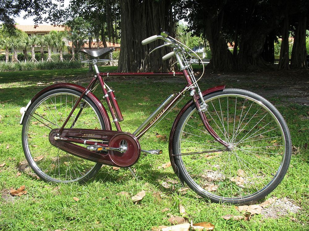
PC210023.jpgHi - here's a picture with the cover off. I spent a fair amount of time with this yesterday. It works great; the only thing I can't figure out is how do the wires get into their respective spots through the cover.
12-09-11 | 04:19 PM
#14
Senior Member
Joined: Sep 2009
Posts: 424
Likes: 1
From: Boston, MA
Bikes: 1983 Peugeot UO14, KHS Green-Heavily modified, 1972 Raleigh Sprite 27" (work in progress)

image originally from this guys photo-stream:
https://www.flickr.com/photos/4361252...th/4044244349/
No longer recommend this wiring scheme, it is not to factory spec and doesn't rectify current properly in my testing.
Last edited by Fenway; 03-18-12 at 11:13 AM. Reason: No longer recommend this wiring scheme, it is not to factory spec and doesn't rectify current properly in my testing.
03-17-12 | 04:58 PM
#15
Senior Member
Joined: Sep 2009
Posts: 424
Likes: 1
From: Boston, MA
Bikes: 1983 Peugeot UO14, KHS Green-Heavily modified, 1972 Raleigh Sprite 27" (work in progress)
Sturmey Archer Lighting Systems PART I
Direct link to image album if one requires to see the posted images in a larger and clearer format
IDENTIFICATION OF DAU/FSU/DBU UNITS
There appears to be confusion that the Dry Accumulator Unit (DAU) is the same as the Filter Switch Unit (FSU), which is not the case.

The Dry Accumulator Unit (DAU) was produced ~1946-1950. The Dynohub constantly recharged (3) 2 Volt lead acid batteries through two rectifying diodes, where the Dynohub always supplied current to the lamps through the batteries. This unit can be identified by the 3 terminals arrayed around a longer center terminal (4 total) and a small rivet holding the top section in place without a serviceable knob to easily remove the rectifier unit assembly from the top of the battery tube. This requires more effort to disassemble which is detailed in the final common repair photo in the section below. Because the batteries are integral to the circuit one must always have at least a dead set of batteries inside the battery tube to ensure a completed circuit, otherwise only the head lamp will light (in my testing).

The Filter Switch Unit (FSU) was introduced as a replacement to the DAU as the rechargeable lead acid batteries of the era tended to leak. The FSU had a rectifying circuit which provided Dynohub current directly to the lights and when that current was insufficient, automatically switched over the to the battery current from (3) 1.5 volt D batteries. There was no recharging of batteries, either the Dynohub was directly powering the lamps through the rectifying circuit or when automatically switched off by the circuit the lamps were operating like a flashlight directly from the batteries. This unit can be identified by the 3 terminals arrayed around a longer center terminal (4 total) or later a 4 terminal pattern forming a square field, and no removable section at the top of the tube. There will be service knob allowing the top of the unit (rectifier assembly) to be removed from the top of the tube. Without batteries in the unit the lamps will function are a normal Dynohub lighting system without stand-lights.

The Dry Battery Unit (DBU) provided switched current from (3) 1.5 volt batteries and had no connection to a Dynohub. It had no rectification of current or charging of batteries. Essentially allow the lamps to be used like flashlights when switched on. This unit can be identified by the presence of only two terminals, one short and one long. Either the lamps are switch to battery operation (giant flashlight), off, or to Dynohub operation, there is no real stand-light option unless one is manually flicking the switch over to battery operation at every stop.
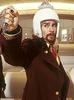
Wiring for STURMEY ARCHER LIGHTING & DAU/FSU/DBU UNITS
Here are the wiring diagrams from the service manual. The Filter Switch Unit (FSU) wiring diagram shown is the same for the Dry Accumulator Unit (DAU), I do not recommend using the hand drawn diagram earlier in this thread as in my testing does not properly rectify current and isn't to the factory wiring specifications below.
ALWAYS USE PROTECTED RECHARGEABLE BATTERIES IN FSU/DAU UNITS TO AVOID POTENTIALLY UNPLEASANT EFFECTS FROM STRAY VOLTAGE. DO NOT USE MORE THAN THE EQUIVALENT OF (3) 1.2 VOLT RECHARGEABLE BATTERIES IN THESE UNITS!
(At this time I recommend Sanyo Eneloop batteries)


The diagrams above I believe are the clearest. However should you require additional information please refer to the diagrams in PART II from other service manuals.
IDENTIFICATION OF DAU/FSU/DBU UNITS
There appears to be confusion that the Dry Accumulator Unit (DAU) is the same as the Filter Switch Unit (FSU), which is not the case.
The Dry Accumulator Unit (DAU) was produced ~1946-1950. The Dynohub constantly recharged (3) 2 Volt lead acid batteries through two rectifying diodes, where the Dynohub always supplied current to the lamps through the batteries. This unit can be identified by the 3 terminals arrayed around a longer center terminal (4 total) and a small rivet holding the top section in place without a serviceable knob to easily remove the rectifier unit assembly from the top of the battery tube. This requires more effort to disassemble which is detailed in the final common repair photo in the section below. Because the batteries are integral to the circuit one must always have at least a dead set of batteries inside the battery tube to ensure a completed circuit, otherwise only the head lamp will light (in my testing).
The Filter Switch Unit (FSU) was introduced as a replacement to the DAU as the rechargeable lead acid batteries of the era tended to leak. The FSU had a rectifying circuit which provided Dynohub current directly to the lights and when that current was insufficient, automatically switched over the to the battery current from (3) 1.5 volt D batteries. There was no recharging of batteries, either the Dynohub was directly powering the lamps through the rectifying circuit or when automatically switched off by the circuit the lamps were operating like a flashlight directly from the batteries. This unit can be identified by the 3 terminals arrayed around a longer center terminal (4 total) or later a 4 terminal pattern forming a square field, and no removable section at the top of the tube. There will be service knob allowing the top of the unit (rectifier assembly) to be removed from the top of the tube. Without batteries in the unit the lamps will function are a normal Dynohub lighting system without stand-lights.
The Dry Battery Unit (DBU) provided switched current from (3) 1.5 volt batteries and had no connection to a Dynohub. It had no rectification of current or charging of batteries. Essentially allow the lamps to be used like flashlights when switched on. This unit can be identified by the presence of only two terminals, one short and one long. Either the lamps are switch to battery operation (giant flashlight), off, or to Dynohub operation, there is no real stand-light option unless one is manually flicking the switch over to battery operation at every stop.
Wiring for STURMEY ARCHER LIGHTING & DAU/FSU/DBU UNITS
Here are the wiring diagrams from the service manual. The Filter Switch Unit (FSU) wiring diagram shown is the same for the Dry Accumulator Unit (DAU), I do not recommend using the hand drawn diagram earlier in this thread as in my testing does not properly rectify current and isn't to the factory wiring specifications below.
ALWAYS USE PROTECTED RECHARGEABLE BATTERIES IN FSU/DAU UNITS TO AVOID POTENTIALLY UNPLEASANT EFFECTS FROM STRAY VOLTAGE. DO NOT USE MORE THAN THE EQUIVALENT OF (3) 1.2 VOLT RECHARGEABLE BATTERIES IN THESE UNITS!
(At this time I recommend Sanyo Eneloop batteries)
The diagrams above I believe are the clearest. However should you require additional information please refer to the diagrams in PART II from other service manuals.
Last edited by Fenway; 04-21-12 at 10:26 AM. Reason: Split into 2 posts
03-19-12 | 04:10 PM
#16
Thread Starter
MikesBikes
Joined: Dec 2010
Posts: 20
Likes: 0
From: New London, CT
Bikes: 1969 Raleigh Superbe; 1951 Raleigh Clubman; 1980 Raleigh Record
Thanks for all the great information. I was able to figure out most of the story from my pitiful knowledge of AC, DC, rectifiers and such, along with some experimentation. It was good to see confirmation that the center setting on the switch was just not used. I was wondering why there were three settings.
04-21-12 | 10:18 AM
#17
Senior Member
Joined: Sep 2009
Posts: 424
Likes: 1
From: Boston, MA
Bikes: 1983 Peugeot UO14, KHS Green-Heavily modified, 1972 Raleigh Sprite 27" (work in progress)
Sturmey Archer Lighting Systems PART II
Direct link to image album if one requires to see the posted images in a larger and clearer format
The diagrams above in PART I, I believe are the clearest. However should you require additional information please refer to the diagrams below.


Wiring Key STURMEY ARCHER LIGHTING & DAU/FSU/DBU UNITS

So one may understand what part numbers go to what lengths & connectors of wire which existed. Earlier versions use eyelet tabs and terminal connectors. Later versions used "butt" style plugs into cylinder shaped terminals. Both terminals/connector types can still be obtained from hardware and electronic stores like RadioShack for home made replacement wiring schemes.
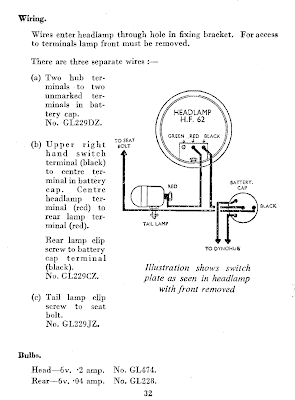
REPAIR OF DAU/FSU UNITS
Directions for repairing a DAU unit which may also apply for repairing a FSU unit. Over tightening of the central terminal or cap nut can twist the internal connections to the bottoms of the terminals resulting in a faulty connection to the rectifying circuitry. If this occurs it is only a matter of carefully disassembling the unit to the point that the tabs can be bent back into position (or re-soldered if necessary), reoriented properly and properly reseated in the battery tube. The photos below should be clear enough to allow one to figure this out.


Lamp information
See this post for HF-62 HF-625 HF-63 lamps manufactured ~1940-1960
https://www.bikeforums.net/showthread...natomical-Tour
"HF-62 is listed in catalogs as being "complete" with a 2 amp bulb "for Dyno-Luxe" and the HF-63 complete with a 3 amp bulb. The tail lamps (TL series with different numbers) had 3 different series with very different styles back then as well. The HF-62 is always shown wired to a GH6 dynohub with the Dyno-Luxe in the circuit. the HF-625 is always wired to AG-3 or AG-4 hubs (with or without a battery), and the HF-63 is always wired to GH6 hubs with or without a Dry Battery Unit but never a Dry Accumulator or Filter Switch Unit. Wiring was listed as GL or GZ base on whether it had the brass butt plugs or the earlier eyelet terminal connectors.
I assume the different early lamp models were the same save for the bulbs and the included flex wires. Later on there were all chrome versions of these style lamps before the two more bullet sized shapes with the different plug style innards were produced. I didn't even realize there were two sizes of the bullet shaped chrome lamps until I accidentally bought one off Ebay. According to 1950s literature, once the bullet shape had become standard, the larger ones were referred to as "Roadster" while the smaller ones were "Sports" models."
Recommended ready made LED bulb replacements:
Red LED tail light bulb with stand-light capacitor built in & meets European safety standards
https://www.compasscycle.com/lighting_led_tail_bulb.html
On the "upgrade" column:
Reflectalite's large selection of LED head & tail light replacement bulbs
https://www.ebay.com/itm/LED-LIGHT-BU...item3a8004d73f
https://www.bikeco.co.uk/index.php?mo...ail&itemid=454
or
White headlamp LED bulb, scroll down on this page.
https://www.home.earthlink.net/~steinborn/gentlemancyclistmerchandise.htm
Also see:
Reflectalites "Nicelight" voltage regulators
Research into improving Sturmey Archer lights and the functioning of GH-6 Dynohubs.
https://minisystem.blogspot.com/
The diagrams above in PART I, I believe are the clearest. However should you require additional information please refer to the diagrams below.
Wiring Key STURMEY ARCHER LIGHTING & DAU/FSU/DBU UNITS
So one may understand what part numbers go to what lengths & connectors of wire which existed. Earlier versions use eyelet tabs and terminal connectors. Later versions used "butt" style plugs into cylinder shaped terminals. Both terminals/connector types can still be obtained from hardware and electronic stores like RadioShack for home made replacement wiring schemes.
REPAIR OF DAU/FSU UNITS
Directions for repairing a DAU unit which may also apply for repairing a FSU unit. Over tightening of the central terminal or cap nut can twist the internal connections to the bottoms of the terminals resulting in a faulty connection to the rectifying circuitry. If this occurs it is only a matter of carefully disassembling the unit to the point that the tabs can be bent back into position (or re-soldered if necessary), reoriented properly and properly reseated in the battery tube. The photos below should be clear enough to allow one to figure this out.
Lamp information
See this post for HF-62 HF-625 HF-63 lamps manufactured ~1940-1960
https://www.bikeforums.net/showthread...natomical-Tour
"HF-62 is listed in catalogs as being "complete" with a 2 amp bulb "for Dyno-Luxe" and the HF-63 complete with a 3 amp bulb. The tail lamps (TL series with different numbers) had 3 different series with very different styles back then as well. The HF-62 is always shown wired to a GH6 dynohub with the Dyno-Luxe in the circuit. the HF-625 is always wired to AG-3 or AG-4 hubs (with or without a battery), and the HF-63 is always wired to GH6 hubs with or without a Dry Battery Unit but never a Dry Accumulator or Filter Switch Unit. Wiring was listed as GL or GZ base on whether it had the brass butt plugs or the earlier eyelet terminal connectors.
I assume the different early lamp models were the same save for the bulbs and the included flex wires. Later on there were all chrome versions of these style lamps before the two more bullet sized shapes with the different plug style innards were produced. I didn't even realize there were two sizes of the bullet shaped chrome lamps until I accidentally bought one off Ebay. According to 1950s literature, once the bullet shape had become standard, the larger ones were referred to as "Roadster" while the smaller ones were "Sports" models."
Recommended ready made LED bulb replacements:
Red LED tail light bulb with stand-light capacitor built in & meets European safety standards
https://www.compasscycle.com/lighting_led_tail_bulb.html
On the "upgrade" column:
Reflectalite's large selection of LED head & tail light replacement bulbs
https://www.ebay.com/itm/LED-LIGHT-BU...item3a8004d73f
https://www.bikeco.co.uk/index.php?mo...ail&itemid=454
or
White headlamp LED bulb, scroll down on this page.
https://www.home.earthlink.net/~steinborn/gentlemancyclistmerchandise.htm
Also see:
Reflectalites "Nicelight" voltage regulators
Research into improving Sturmey Archer lights and the functioning of GH-6 Dynohubs.
https://minisystem.blogspot.com/
Last edited by Fenway; 04-14-13 at 09:48 AM. Reason: Added more LED replacement bulb suppliers
04-21-12 | 10:34 AM
#18

www.theheadbadge.com


Joined: Sep 2005
Posts: 28,998
Likes: 5,481
From: Southern Florida
Bikes: https://www.theheadbadge.com
 04-21-12 | 06:21 PM
#19
Senior Member
Joined: Jan 2011
Posts: 295
Likes: 0
From: Armenia, Colombia
Bikes: 1961 Raleigh Sports
How does a DAU setup compare to current LED headlamps with standlights? Rather, what complicating issue prevents this design from being used today with LEDs? Battery wear?
Having the lights run off a set of batteries that are constantly being recharged through rectifiers sounds like a pretty simple circuit to setup (Dynamo -> rectifiers -> battery -> headlamp -> tailight) compared to some of the standlight circuits that have been linked here .
.
Having the lights run off a set of batteries that are constantly being recharged through rectifiers sounds like a pretty simple circuit to setup (Dynamo -> rectifiers -> battery -> headlamp -> tailight) compared to some of the standlight circuits that have been linked here
.
04-21-12 | 08:19 PM
#20
Senior Member
Joined: Sep 2009
Posts: 424
Likes: 1
From: Boston, MA
Bikes: 1983 Peugeot UO14, KHS Green-Heavily modified, 1972 Raleigh Sprite 27" (work in progress)
Modern capacitors have made the separate energy storage unit mostly obsolete. That's why one doesn't see them made anymore.
DAUs were invented before the advent of the mini super-capacitors now used to power stand-lights in modern dynamo powered bicycle lights. The lead acid batteries used in the units had the same problem as all old lead acid batteries, in that the constant current recharging them eventually causes the batteries to corrode to the point of leaking and developing memory issues.
FSU units came into being when Sturmey Archer got sick of dealing with leaking battery issues and couldn't obtain a better energy storage solution at the time. Thus the switch to a filter switch, where the stand-light was powered by conventional batteries (like a flashlight) whenever the dynamo current was detected to have cut out.
The DBU units are essentially a flashlight setup akin to modern battery powered lights. At the time it would been prohibitive to stick D batteries into both the head and tail lights for such low input, therefore the DAU/FSU battery tube was reused with a simple switch through the headlight. Though I must say that I have encountered one British Miller head lamp from the late 1950s which used a large EverReady 9 or 12? volt flashlight battery with a remotely wired push button on/off switch.
Sanyo Eneloop batteries should have better longevity than the original lead acid batteries in the DAU/FSU units and never leak. However, since they are 1.2-1.5volts vs. 1.5-2volts of the original batteries -the battery powered stand-light illumination will never be quite as bright as the original bulbs or the maximum potential illumination from modern LED bulbs. Unless of course someone can create a custom battery pack or protected capacitor (the capacitor could be potentially lethal if poorly designed...hence my tendency to want to stay with protected circuit rechargeable batteries) to fit inside the tubes with the proper connections.
04-22-12 | 12:43 AM
#21

Senior Member
Joined: Dec 2011
Posts: 90
Likes: 3
From: Toronto
Fenway knows his stuff. I must admit to only becoming recently acquainted with SA DAU/FSU devices.
There are a variety of DIY standlight circuits out there that are pretty simple. At their simplest, they are just a small network of diodes and resistors that ensure the supercapacitor discharges through the LEDs at some limited current to allow a reasonable standlight duration.
I tried a lithium ion powered charger/standlight, which worked OK but needed improvement. Eventually I just figured out how to use supercapacitors instead.
02-12-17 | 06:42 PM
#22
Newbie
Joined: Feb 2017
Posts: 15
Likes: 0
Bikes: Raleigh Superbe, Royal Enfield, Raleigh Chiltern
hey guys just wandering what happens if the wiring is set up wrong i need a bit of help with my FSU which i assume is what it is, i have gone on one 7 mile appro journey and disconnected it. can setting it up wrong cause de magnetising of the dynamo?
04-24-19 | 02:33 AM
#23
Junior Member

Joined: Aug 2015
Posts: 97
Likes: 6
From: Midlands
Bikes: Hetchins, Dawes, Raleigh, Holdsworth, Standard Cycle Co, and others
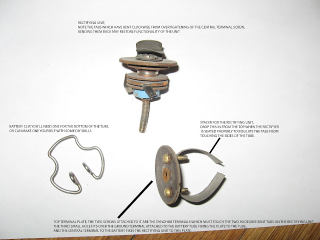
Humber Bicycle
I'm not familiar with the unit but according to the Sturmey Archer Heritage site its basically a bridge rectifier with some dry cell batteries.
here's the diagram...if I'm reading it correctly (and I think I am) you'd hook the Dynohub to the two posts that aren't "+" or "-", and hook the lights to the "+" and "-" posts.
Can't help you with the chrome cover, sorry
here's the diagram...if I'm reading it correctly (and I think I am) you'd hook the Dynohub to the two posts that aren't "+" or "-", and hook the lights to the "+" and "-" posts.
Can't help you with the chrome cover, sorry
The dynohub is generating power, so Im guessing that the battery unit will not work if the batteries have failed.
Batteries can be sourced but I am concerned that the rectifier will have deteriorated. Have you seen a circuit diagram documented anywhere.
I have yet to disassemble the unit, and it looks like being a problem after so long, so I want to be as prepared as possible.
04-24-19 | 02:18 PM
#24

Senior Member

Joined: Jul 2006
Posts: 11,471
Likes: 4,868
From: San Jose (Willow Glen) Ca
Bikes: Kirk Custom JK Special, 86 De Rosa Pro, '84 Team Miyata,(dura ace old school) 80?? SR Semi-Pro 600 Arabesque
I'm not familiar with the unit but according to the Sturmey Archer Heritage site its basically a bridge rectifier with some dry cell batteries.
here's the diagram...if I'm reading it correctly (and I think I am) you'd hook the Dynohub to the two posts that aren't "+" or "-", and hook the lights to the "+" and "-" posts.
Can't help you with the chrome cover, sorry
here's the diagram...if I'm reading it correctly (and I think I am) you'd hook the Dynohub to the two posts that aren't "+" or "-", and hook the lights to the "+" and "-" posts.
Can't help you with the chrome cover, sorry
__________________
Life is too short not to ride the best bike you have, as much as you can.
Life is too short not to ride the best bike you have, as much as you can.

