


Electronics experts, please tell me if this homebrew LED dynamo light will work
 10-31-11, 10:39 AM
#1

multimodal commuter
Thread Starter

Join Date: Nov 2006
Location: NJ, NYC, LI
Posts: 19,808
Bikes: 1940s Fothergill, 1959 Allegro Special, 1963? Claud Butler Olympic Sprint, Lambert 'Clubman', 1974 Fuji "the Ace", 1976 Holdsworth 650b conversion rando bike, 1983 Trek 720 tourer, 1984 Counterpoint Opus II, 1993 Basso Gap, 2010 Downtube 8h, and...
Mentioned: 584 Post(s)
Tagged: 0 Thread(s)
Quoted: 1908 Post(s)
Liked 574 Times
in
339 Posts
Electronics experts, please tell me if this homebrew LED dynamo light will work
I want to convert an old (1940's or 50's) headlight and taillight to run LED's. Both have a single wire hookup, using the bicycle frame as the other wire. I would like to try to run LED's that way.
I realize the LED's require DC while the dynamo provides AC. I know how to solder up four schottky diodes to convert the AC to DC, but that requires running two wires, which I'm trying to avoid.

So here (attached) is my idea. I'll put a single schottky diode in series with each LED (one front, one rear) to prevent reverse voltage from destroying the LED's. One light will have a wire from the hub to the + point on the LED, the other will have a wire from the frame to the + point on the LED, so the lights will flash alternately. I have been told the flashing will drive me crazy, but I am willing to take that chance.
Each light will have an adequate heat sink and lens, but no switch and no capacitor. I'm currently running lights without switch and capacitor, and that's not a problem.
The dynamo will be a Sturmey Archer GH6 6v 1.8W dynohub from the 50's. The headlight will be something like this, and the taillight something like this.
So, my question to those of you who understand this stuff, please tell me if this will work. Any and all suggestions will be welcome.
Thanks in advance!
Edit, oops, I seem to have attached two versions of the schematic. The one above, I think, is easier to follow.
I realize the LED's require DC while the dynamo provides AC. I know how to solder up four schottky diodes to convert the AC to DC, but that requires running two wires, which I'm trying to avoid.
So here (attached) is my idea. I'll put a single schottky diode in series with each LED (one front, one rear) to prevent reverse voltage from destroying the LED's. One light will have a wire from the hub to the + point on the LED, the other will have a wire from the frame to the + point on the LED, so the lights will flash alternately. I have been told the flashing will drive me crazy, but I am willing to take that chance.
Each light will have an adequate heat sink and lens, but no switch and no capacitor. I'm currently running lights without switch and capacitor, and that's not a problem.
The dynamo will be a Sturmey Archer GH6 6v 1.8W dynohub from the 50's. The headlight will be something like this, and the taillight something like this.
So, my question to those of you who understand this stuff, please tell me if this will work. Any and all suggestions will be welcome.
Thanks in advance!
Edit, oops, I seem to have attached two versions of the schematic. The one above, I think, is easier to follow.
Last edited by rhm; 10-31-11 at 10:42 AM.
 10-31-11, 04:40 PM
#2


Randomhead
Join Date: Aug 2008
Location: Happy Valley, Pennsylvania
Posts: 24,399
Mentioned: 0 Post(s)
Tagged: 0 Thread(s)
Quoted: 4 Post(s)
Liked 3,699 Times
in
2,519 Posts
I'm too lazy to think through your circuit, but since nobody has chimed in, I'll just say what my approach would be.
there is no reason not to use the frame as a ground with a regular bridge rectifier. All of the dynohubs I'm familiar with ground the frame even though they might have a second wire. You need a wire to each light from the dyno, I don't necessarily see the advantage of putting the leds in series. Just put a bridge front and back.
there is no reason not to use the frame as a ground with a regular bridge rectifier. All of the dynohubs I'm familiar with ground the frame even though they might have a second wire. You need a wire to each light from the dyno, I don't necessarily see the advantage of putting the leds in series. Just put a bridge front and back.
10-31-11, 05:43 PM
#3
Senior Member
Join Date: Nov 2009
Posts: 555
Mentioned: 0 Post(s)
Tagged: 0 Thread(s)
Quoted: 31 Post(s)
Likes: 0
Liked 10 Times
in
8 Posts
The circuit you devised is a half wave rectifier. Each light will be lit only half the time. The front and rear are being lit at different times. It's not really necessary. You can design a half wave rectifier with only one diode.
11-01-11, 12:44 PM
#4
multimodal commuter
Thread Starter
Join Date: Nov 2006
Location: NJ, NYC, LI
Posts: 19,808
Bikes: 1940s Fothergill, 1959 Allegro Special, 1963? Claud Butler Olympic Sprint, Lambert 'Clubman', 1974 Fuji "the Ace", 1976 Holdsworth 650b conversion rando bike, 1983 Trek 720 tourer, 1984 Counterpoint Opus II, 1993 Basso Gap, 2010 Downtube 8h, and...
Mentioned: 584 Post(s)
Tagged: 0 Thread(s)
Quoted: 1908 Post(s)
Liked 574 Times
in
339 Posts
I thank you both for your replies!
To clarify, I realize there are pretty much infinite ways I can do this differently. I'm just looking for the simplest system possible. If I can use two schottky diodes rather than four, or eight, I'd like to use two. The more complicated the system, the more difficult it is to find the problem when something goes wrong. I built the lights on this bike, for example, a few months ago:
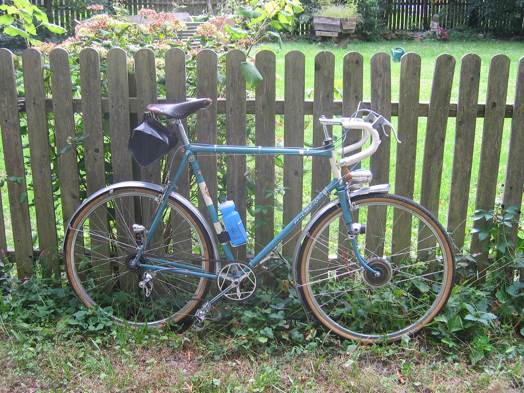
(disregard the battery light on the right fork blade; it's redundant, not part of the dynamo system)
The lights worked very well at first, but one day stopped working. Most of the soldered connections are encased in heat shrink tubing, and there must be a dozen or more of them; to find the problem I will have to start opening them up, one by one, and in the end it is likely I'll have to basically rebuild the system from start to finish. And it's happened before that I end up fixing the problem without every diagnosing it.
Unterhausen, on the bicycle shown above, there is plenty of room for bridges inside the light housings; but in other cases there isn't.
As to the advantage of putting the LED's in series, I don't know. Someone recommended that, so I did it.
SB, yes, I understand in my circuit each light is lit half the time; one light, or the other, is lit at all times. I assume this uses all of the power generated.
If I used only one diode, I think I don't understand. Wouldn't I have to waste half of the power generated?
Again, thanks in advance for any advice you have. My central question remains: will this work?
To clarify, I realize there are pretty much infinite ways I can do this differently. I'm just looking for the simplest system possible. If I can use two schottky diodes rather than four, or eight, I'd like to use two. The more complicated the system, the more difficult it is to find the problem when something goes wrong. I built the lights on this bike, for example, a few months ago:
(disregard the battery light on the right fork blade; it's redundant, not part of the dynamo system)
The lights worked very well at first, but one day stopped working. Most of the soldered connections are encased in heat shrink tubing, and there must be a dozen or more of them; to find the problem I will have to start opening them up, one by one, and in the end it is likely I'll have to basically rebuild the system from start to finish. And it's happened before that I end up fixing the problem without every diagnosing it.
Unterhausen, on the bicycle shown above, there is plenty of room for bridges inside the light housings; but in other cases there isn't.
As to the advantage of putting the LED's in series, I don't know. Someone recommended that, so I did it.
SB, yes, I understand in my circuit each light is lit half the time; one light, or the other, is lit at all times. I assume this uses all of the power generated.
If I used only one diode, I think I don't understand. Wouldn't I have to waste half of the power generated?
Again, thanks in advance for any advice you have. My central question remains: will this work?
11-01-11, 07:10 PM
#5
Senior Member
Join Date: Apr 2007
Posts: 130
Mentioned: 0 Post(s)
Tagged: 0 Thread(s)
Quoted: 0 Post(s)
Likes: 0
Liked 0 Times
in
0 Posts
Yes, it will work. In fact, the Schottky diodes are not doing anything useful in that circuit. You can get rid of them. The forward conducting LED will itself limit the voltage to protect the non-conducting one.
11-02-11, 06:56 AM
#6
multimodal commuter
Thread Starter
Join Date: Nov 2006
Location: NJ, NYC, LI
Posts: 19,808
Bikes: 1940s Fothergill, 1959 Allegro Special, 1963? Claud Butler Olympic Sprint, Lambert 'Clubman', 1974 Fuji "the Ace", 1976 Holdsworth 650b conversion rando bike, 1983 Trek 720 tourer, 1984 Counterpoint Opus II, 1993 Basso Gap, 2010 Downtube 8h, and...
Mentioned: 584 Post(s)
Tagged: 0 Thread(s)
Quoted: 1908 Post(s)
Liked 574 Times
in
339 Posts
Thanks! I'll give it a try.
11-04-11, 09:00 AM
#7
Senior Member
Join Date: Nov 2009
Posts: 555
Mentioned: 0 Post(s)
Tagged: 0 Thread(s)
Quoted: 31 Post(s)
Likes: 0
Liked 10 Times
in
8 Posts
If one wishes to use the LED as both a half wave rectifier and a light source, one would be advised to use two LED's with opposite polarity. This way there will always be a load on the dynamo and high open circuit voltages will not appear at the terminals of the non-conducting LED.
The problem with this approach, is that should one of the LED's (or the wiring to it fail), the remaining LED will most likely be toast. The solution is to use a zener diode overvoltage protection. (The zener protection voltage should be lower than the LED's max reverse voltage spec and greater than the LED's forward voltage). This will add two zeners to the circuit. The best place to mount them is at the dynamo terminals, so they will cut in regardless of which wires leading to the LED's should fail.
11-04-11, 09:09 AM
#8
Senior Member
Join Date: Nov 2009
Posts: 555
Mentioned: 0 Post(s)
Tagged: 0 Thread(s)
Quoted: 31 Post(s)
Likes: 0
Liked 10 Times
in
8 Posts
Most of the soldered connections are encased in heat shrink tubing, and there must be a dozen or more of them; to find the problem I will have to start opening them up, one by one, and in the end it is likely I'll have to basically rebuild the system from start to finish. And it's happened before that I end up fixing the problem without every diagnosing it.
11-04-11, 08:46 PM
#9
Senior Member
Join Date: Apr 2007
Posts: 130
Mentioned: 0 Post(s)
Tagged: 0 Thread(s)
Quoted: 0 Post(s)
Likes: 0
Liked 0 Times
in
0 Posts
The OP's circuit has the LEDs wired opposite polarity so no worry about reverse voltage damage. Zeners would be a good protection measure but I think the OP wanted the simplest possible design.

Thread
Thread Starter
Forum
Replies
Last Post
jyl
Electronics, Lighting, & Gadgets
8
09-26-14 08:24 PM
