


Blade bending blocks
 03-09-13 | 11:18 AM
#26
Randomhead
Joined: Aug 2008
Posts: 25,930
Likes: 4,825
From: Happy Valley, Pennsylvania
is the "clever and simple stop" from Jamie Swan?
The thing I like about that is the anti-rotation pin, curious if there is an equal and opposite pin under the jaw of the vise on the other side
The thing I like about that is the anti-rotation pin, curious if there is an equal and opposite pin under the jaw of the vise on the other side
 03-09-13 | 11:27 AM
#27

Thread Starter
Senior Member

Joined: Mar 2012
Posts: 1,104
Likes: 48
From: santa barbara CA
03-09-13 | 12:34 PM
#28


Decrepit Member
Joined: Aug 2005
Posts: 10,488
Likes: 92
From: Santa Rosa, California
Bikes: Waterford 953 RS-22, several Paramounts
It's David Kirk: https://www.kirkframeworks.com/blog/2...meset-part-iv/
 03-09-13 | 06:17 PM
#29

Senior Member
Joined: Apr 2010
Posts: 3,081
Likes: 10
From: vermont
Bikes: Many
It's David Kirk: https://www.kirkframeworks.com/blog/2...meset-part-iv/
03-11-13 | 07:44 PM
#30
Thread Starter
Senior Member
Joined: Mar 2012
Posts: 1,104
Likes: 48
From: santa barbara CA
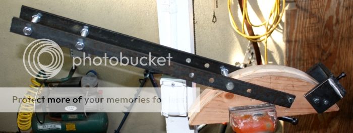
Made a little progress, saddles are done, blocks glued together. Don't ask why the the blocks are different widths, just wasn't thinking, oh well. My stick welding skills are good enough to hold low tech stuff together but pretty crappy looking. I used 6011 3/16" rod at 105amps for the thicker plate, 6011 1/8" rod 90amps for the thinner plate, that has an interior fillet. Local scrap yard is my source for mtl, if I'm there and see something I think I can use I buy, $.10lb for steel, $1.00 for al. I had the mtl used here on hand so that's what I used. Next is making the arms/levers and figuring out where best to position the pivot. When thats done I hope to have choosen a wheel or something to slide/roll on the fork blades.
The holes across the top are tapped 3/8"x24tpi to accept a bolt for the hold down, probably terminate in a piece of channel with a flat ground on it. The holes on the sides are for an arm/lever pivot and a support dowel/bolt. Suggestions welcomed.
thanks, Brian


The holes across the top are tapped 3/8"x24tpi to accept a bolt for the hold down, probably terminate in a piece of channel with a flat ground on it. The holes on the sides are for an arm/lever pivot and a support dowel/bolt. Suggestions welcomed.
thanks, Brian
Last edited by calstar; 03-11-13 at 07:57 PM.
03-13-13 | 04:12 AM
#31
Senior Member
Joined: Apr 2010
Posts: 3,081
Likes: 10
From: vermont
Bikes: Many
Made a little progress, saddles are done, blocks glued together. Don't ask why the the blocks are different widths, just wasn't thinking, oh well. My stick welding skills are good enough to hold low tech stuff together but pretty crappy looking. I used 6011 3/16" rod at 105amps for the thicker plate, 6011 1/8" rod 90amps for the thinner plate, that has an interior fillet. Local scrap yard is my source for mtl, if I'm there and see something I think I can use I buy, $.10lb for steel, $1.00 for al. I had the mtl used here on hand so that's what I used. Next is making the arms/levers and figuring out where best to position the pivot. When thats done I hope to have choosen a wheel or something to slide/roll on the fork blades.
The holes across the top are tapped 3/8"x24tpi to accept a bolt for the hold down, probably terminate in a piece of channel with a flat ground on it. The holes on the sides are for an arm/lever pivot and a support dowel/bolt. Suggestions welcomed.
thanks, Brian
The holes across the top are tapped 3/8"x24tpi to accept a bolt for the hold down, probably terminate in a piece of channel with a flat ground on it. The holes on the sides are for an arm/lever pivot and a support dowel/bolt. Suggestions welcomed.
thanks, Brian
It looks good. If you can get some angle iron to bolt through the sides and drill through the wood and angles for your pivot, you will get flanges for clamping/bolting the device to the benchtop.
03-13-13 | 03:44 PM
#32
Thread Starter
Senior Member
Joined: Mar 2012
Posts: 1,104
Likes: 48
From: santa barbara CA
^ ".....you will get flanges for clamping/bolting the device to the benchtop."
I'll most likely clamp it in my vise rather than bolt to a benchtop as I have very limited space.
Will a larger dia wheel make any difference, say 6" compared to 4"? Here are a couple of cast iron prospects, thoughts? It looks like the depth/width of the groove is the same, but the flanges are wider on the 6", no specs are given but eyeballing the 4" the groove looks about 1" wide.
thanks, Brian
4" x 1.5" rated 700lbs

6" x 2"

I'll most likely clamp it in my vise rather than bolt to a benchtop as I have very limited space.
Will a larger dia wheel make any difference, say 6" compared to 4"? Here are a couple of cast iron prospects, thoughts? It looks like the depth/width of the groove is the same, but the flanges are wider on the 6", no specs are given but eyeballing the 4" the groove looks about 1" wide.
thanks, Brian
4" x 1.5" rated 700lbs
6" x 2"
Last edited by calstar; 03-13-13 at 06:01 PM.
03-13-13 | 07:32 PM
#34
Framebuilder
Joined: Dec 2007
Posts: 570
Likes: 0
Agreed about the urethane wheel. You need some give if you are going to be using a wheel in this application. Cast iron would be bad.
03-13-13 | 08:01 PM
#35
Thread Starter
Senior Member
Joined: Mar 2012
Posts: 1,104
Likes: 48
From: santa barbara CA
Thanks for pointing me in the right direction again Eric, I was venturing into the world of "penny wise, pound foolish". I just ordered one.
Live Wire: "You need some give if you are going to be using a wheel in this application. Cast iron would be bad."
This is exactly why I post so much*, you guys are a wealth of knowledge and willing to share it. Speaking of which I didn't know what an acetal bearing was so for those who don't its the generic name for Delrin.
DuPont™ Delrin� acetal resin
Pushing the Limits: Delrin� High Performance Acetal Resin SolutionsDelrin� acetal homopolymer bridges the gap between metals and ordinary plastics with a unique combination of creep resistance, strength, stiffness, hardness, dimensional stability, toughness, fatigue resistance, solvent and fuel resistance, abrasion resistance, low wear and low friction.
The above is from this link, more info if anyone wants it: https://www2.dupont.com/Plastics/en_U...in/Delrin.html
thanks, Brian
* and share whatever knowledge/processes I have/use
Last edited by calstar; 03-14-13 at 10:20 AM.
03-14-13 | 07:04 AM
#36
Senior Member

Joined: Dec 2006
Posts: 1,221
Likes: 24
From: Toronto/Montr�al
Bikes: Eight homemade, three very dusty
Here is a pic of mine. Glued/screwed plywood profiled on a band saw (6" radius) with the groove hand filed on half the circumference. The clamp and lever are from scraps and you can sorta see the stop and the roller (Delrin rod with a groove). It's held in the vise but clamping it to the wall would be great. I've also been through a few forms (all from a single piece of wood) that eventually split from the bending stress. Let's hope this one lasts.

03-14-13 | 09:54 AM
#39
Thread Starter
Senior Member
Joined: Mar 2012
Posts: 1,104
Likes: 48
From: santa barbara CA
Tuz(and others), couple of questions regarding your bender, and thanks for the pic.
The hole on top of the lever arm is to insert a pipe for leverage, right? That's a good idea, lot easier to store the bender without a long lever arm. I've cut my lever arms at 28"(the flat stock) but now I'm thinking about changing it to short arms with an attachable/insertable pipe for the mechanical advantage.
How did you determine the distance of the roller from the track? Trial and error?I was planning on positioning mine about 10" away from the track/groove with additional holes drilled in the arms to change that distance if I feel the need. I guess thats partly dependent on the arms pivot location. Some designs have the pivot near the end and base of the block, which I'm tending towards, while others, like yours, are more centered.
Any other pics of DIYs out there?
thanks, Brian
Last edited by calstar; 03-14-13 at 10:27 AM.
03-14-13 | 10:25 AM
#40
Senior Member
Joined: Dec 2006
Posts: 1,221
Likes: 24
From: Toronto/Montr�al
Bikes: Eight homemade, three very dusty
Yes the hole fits a 7/8" dia. lever, over which I slipped an Oury grip for fun.
I didn't give much though to the location of the roller. It could be a bit lower, there is ample room to insert the blade when the lever is up. I'm not sure what difference it makes? Lower means more mechanical advantage I guess, but if you use a long enough lever... It's also nice if the roller follows the form closely, but I don't think it really matters. I put the pivot there in order to leave room to clamp the bender in a vice.
Another thing to keep in mind is to put the mounting bolt far from the edge. Depending on the wood and grain orientation, if it's too close the bolt could rip through. And use 3/8" bolts, 1/4" will bend. 'been there...
03-14-13 | 03:14 PM
#41
Senior Member
Joined: Dec 2006
Posts: 1,221
Likes: 24
From: Toronto/Montr�al
Bikes: Eight homemade, three very dusty
03-14-13 | 07:04 PM
#42
Senior Member
Joined: Apr 2011
Posts: 73
Likes: 2
How did you determine the distance of the roller from the track? Trial and error?I was planning on positioning mine about 10" away from the track/groove with additional holes drilled in the arms to change that distance if I feel the need. I guess thats partly dependent on the arms pivot location. Some designs have the pivot near the end and base of the block, which I'm tending towards, while others, like yours, are more centered.
__________________
cforestryan.com
cforestryan.com
03-15-13 | 12:03 PM
#43
Thread Starter
Senior Member
Joined: Mar 2012
Posts: 1,104
Likes: 48
From: santa barbara CA
Brian
 03-16-13 | 12:16 PM
#45
Senior Member
Joined: Apr 2011
Posts: 73
Likes: 2
How are you going to anchor the tip under that bolt? I use a section of galvanized pipe cut in half, it works, but has to be positioned each time carefully. Maybe you could do practice bends on electrical conduit as you work it out.
__________________
cforestryan.com
cforestryan.com
03-16-13 | 12:32 PM
#46
Thread Starter
Senior Member
Joined: Mar 2012
Posts: 1,104
Likes: 48
From: santa barbara CA
Brian
like this piece from the Hammill
Last edited by calstar; 03-17-13 at 09:48 AM.
03-17-13 | 04:47 AM
#47
Senior Member
Joined: Apr 2010
Posts: 3,081
Likes: 10
From: vermont
Bikes: Many
'looking good! I have some other things to show, both victory and failure but my computer is getting serviced this weekend and I can't get my images from the camera to the internet.
It is very interesting but the bending geometry used on many of these devices wouldn't work for most tube bending situations. You usually have to wrap the tooling all around the "moment" (where the bend happens) and the fulcrum of the handle would have to be in the center of the bend rad, but due to the diameter and thickness of where the bend takes place it works.
It is very interesting but the bending geometry used on many of these devices wouldn't work for most tube bending situations. You usually have to wrap the tooling all around the "moment" (where the bend happens) and the fulcrum of the handle would have to be in the center of the bend rad, but due to the diameter and thickness of where the bend takes place it works.
Last edited by ftwelder; 03-17-13 at 05:21 AM.
03-17-13 | 10:10 AM
#48
Thread Starter
Senior Member
Joined: Mar 2012
Posts: 1,104
Likes: 48
From: santa barbara CA
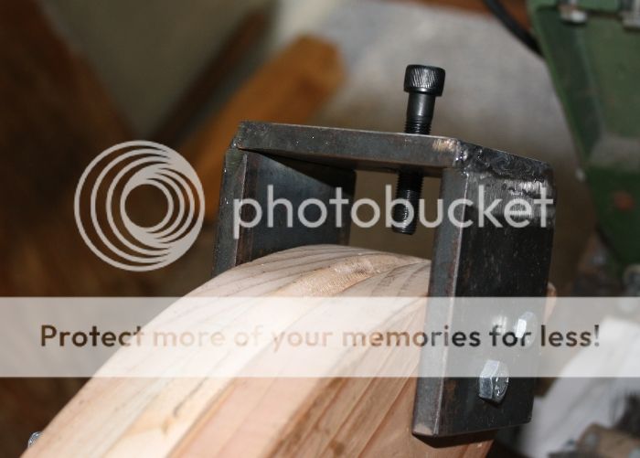
tubing hold down
Little(little by little!) more done yesterday with funky horizontal hf bandsaw from CL, grinding wheel and file. Used gun bluing paste which is fast and easy, couple of minutes(my friend Karl blued an old Stumpjumper frame, looks pretty nice). I still will need to tune the final shape but this is it for now, left a long "tail" on it for easier handling/positioning between the screw and tube.
Brian
the stick welds at the corner aren't penetrating enough(I didn't want to blow the corner off) but the rest of the fillet is burned in for full penetration, plenty strong for this


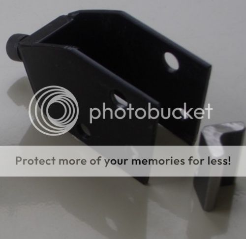
angle stock and piece, I screwed up the al angle I had so went with this, probably better in the long run
blued

Brian
the stick welds at the corner aren't penetrating enough(I didn't want to blow the corner off) but the rest of the fillet is burned in for full penetration, plenty strong for this
angle stock and piece, I screwed up the al angle I had so went with this, probably better in the long run
blued
Last edited by calstar; 03-17-13 at 09:26 PM.
03-21-13 | 10:31 AM
#49
Thread Starter
Senior Member
Joined: Mar 2012
Posts: 1,104
Likes: 48
From: santa barbara CA
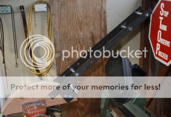
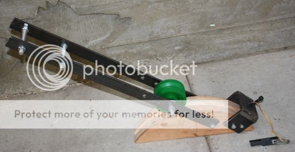
I got the wheel from McMaster, the pic shows it on the 9" radius block. The basic structure is pretty much done but I still have to play around and find optimal pivot placement for the lever arm and some other various tuning. I bent some 1/2" emt to test it and will most likely need to add some length to the arm, it was doable but a little hard with the length it is now.
I've used 1/2" bolts and all thread to space the arms since the 6" block is 3/8 thicker, this allows me to switch the arm between the blocks and adjust accordingly. I may run the 6" through the planer to get the same thickness although I generally don't like running short pieces through it.
Brian
I've used 1/2" bolts and all thread to space the arms since the 6" block is 3/8 thicker, this allows me to switch the arm between the blocks and adjust accordingly. I may run the 6" through the planer to get the same thickness although I generally don't like running short pieces through it.
Brian
Last edited by calstar; 03-21-13 at 10:44 AM.