


USB power from dynahub?
 10-24-07, 08:34 AM
#1
Senior Member
Thread Starter

Join Date: Oct 2006
Location: Hammond, LA
Posts: 305
Bikes: 95 Specialized Rockhopper Comp, 92 Specialized Sirrus Triple
Mentioned: 0 Post(s)
Tagged: 0 Thread(s)
Quoted: 0 Post(s)
Likes: 0
Liked 0 Times
in
0 Posts
I can solder, but I'm not really knowledgeable enough to design a circuit from scratch. I know I'd need regulated 5v power at 500mA. Almost every gadget I'd want to carry with me on tour can be charged from via a mini-b connector. My GPS, my cell phone, my Sony Mylo; they all have the ability to charge from a USB port. Hub dynamos seem to put out several times the power required for the job. Has anyone here tried something like this?
 10-24-07, 01:02 PM
#2
Recumbent Evangelist
Join Date: Mar 2005
Location: Kitchener, Ontario
Posts: 2,991
Bikes: Rebel Cycles Trike, Trek 7500FX
Mentioned: 0 Post(s)
Tagged: 0 Thread(s)
Quoted: 1 Post(s)
Likes: 0
Liked 0 Times
in
0 Posts
Tried it? No. But it could be done. 5V @ 500mA is only 2.5W, which is easily produced by almost any generator. You'd basically need a 5V low-dropout voltage regulator, a few beefy capacitors, and whatever else the regulator needs to operate.
However, I've got a better idea: why not use a small solar panel instead? It would continue to charge your gadgets even when your bike isn't moving (ie. taking a rest or setting up camp), and would draw less power from your legs.
However, I've got a better idea: why not use a small solar panel instead? It would continue to charge your gadgets even when your bike isn't moving (ie. taking a rest or setting up camp), and would draw less power from your legs.
 10-28-07, 04:02 PM
#4
Scott

Join Date: Jun 2006
Posts: 2,393
Bikes: Too Many
Mentioned: 0 Post(s)
Tagged: 0 Thread(s)
Quoted: 1 Post(s)
Likes: 0
Liked 1 Time
in
1 Post
Yes, and it's easy! You just need 4 NiMH batteries between a bridge rectifier and USB connector. The 4 batteries will regulate both voltage and current for whatever device you plug into the USB connector. Easiest way to wire in a connector is to purchase a cheap USB extension cable and cut off the end that sticks in the USB connector in the computer or hub. Strip some of the cable casing and find 4 wires that should be colored RED (pin #1), WHITE (pin #2), GREEN (pin #3), and BLACK (pin #4). Cut the Green and White wires flush with the cable casing as these are the data lines and will not be used. The Red wire is +5 volt and the Black wire is the ground wire. Connect the Red wire to Positive and Black wire to negative on the battery pack.
Here is a drawing of the plug so you can double-check your work from the plug with a multimeter.

Here is a diagram of my dynamo powered lighting system with a USB port to power a GPS unit. S1 is open so LED's are not used when powering anything from the USB port.

Here is a drawing of the plug so you can double-check your work from the plug with a multimeter.
Here is a diagram of my dynamo powered lighting system with a USB port to power a GPS unit. S1 is open so LED's are not used when powering anything from the USB port.
10-28-07, 10:26 PM
#5
Senior Member
Join Date: Mar 2004
Location: SF Bay
Posts: 505
Mentioned: 0 Post(s)
Tagged: 0 Thread(s)
Quoted: 0 Post(s)
Likes: 0
Liked 1 Time
in
1 Post
To me that looks like a merry go-round, next to a bunch of churches, next to 2 Starbucks. How bout one of you guys design, market, and produce a product the rest of us can buy? I'd love to have a system that would top off my devices and batteries by either hub power or solar (or both).
10-29-07, 04:38 PM
#6
Senior Member
Thread Starter
Join Date: Oct 2006
Location: Hammond, LA
Posts: 305
Bikes: 95 Specialized Rockhopper Comp, 92 Specialized Sirrus Triple
Mentioned: 0 Post(s)
Tagged: 0 Thread(s)
Quoted: 0 Post(s)
Likes: 0
Liked 0 Times
in
0 Posts
Yes, and it's easy! You just need 4 NiMH batteries between a bridge rectifier and USB connector. The 4 batteries will regulate both voltage and current for whatever device you plug into the USB connector. Easiest way to wire in a connector is to purchase a cheap USB extension cable and cut off the end that sticks in the USB connector in the computer or hub. Strip some of the cable casing and find 4 wires that should be colored RED (pin #1), WHITE (pin #2), GREEN (pin #3), and BLACK (pin #4). Cut the Green and White wires flush with the cable casing as these are the data lines and will not be used. The Red wire is +5 volt and the Black wire is the ground wire. Connect the Red wire to Positive and Black wire to negative on the battery pack.
Here is a drawing of the plug so you can double-check your work from the plug with a multimeter.
Here is a diagram of my dynamo powered lighting system with a USB port to power a GPS unit. S1 is open so LED's are not used when powering anything from the USB port.
Here is a drawing of the plug so you can double-check your work from the plug with a multimeter.
Here is a diagram of my dynamo powered lighting system with a USB port to power a GPS unit. S1 is open so LED's are not used when powering anything from the USB port.
Awesome!
11-01-07, 08:03 AM
#7


The Improbable Bulk

Join Date: Jul 2005
Location: Wilkes-Barre, PA
Posts: 8,379
Bikes: Many
Mentioned: 0 Post(s)
Tagged: 0 Thread(s)
Quoted: 5 Post(s)
Likes: 0
Liked 7 Times
in
7 Posts
Not cycling related, but does anyone know if the iTip from Radio Shack for USB is 5 volt? The web site doesn't seem to say, or did I not dig deep enough?
11-01-07, 09:25 AM
#8
Scott
Join Date: Jun 2006
Posts: 2,393
Bikes: Too Many
Mentioned: 0 Post(s)
Tagged: 0 Thread(s)
Quoted: 1 Post(s)
Likes: 0
Liked 1 Time
in
1 Post
When I am running my lights with the dynamo connected I have 120mA of excess current recharging the batteries. If I am not stopping very much I disengage my dynamo for 15 minutes of every hour of riding to prevent overcharging.
I'm going to have to pick up some parts and give it a try. Maybe hook up a multimeter and ride up and down some hills first. I'm buying a new bike with a hub next month, if all goes well. I can't wait. I'll finally be able to install one of these on my bike!
Awesome!
Awesome!
12-26-07, 03:45 AM
#9
Senior Member
Join Date: Jun 2005
Location: Spur TX
Posts: 1,991
Bikes: Schwinn folder; SixThreeZero EvryJourney
Mentioned: 0 Post(s)
Tagged: 0 Thread(s)
Quoted: 0 Post(s)
Likes: 0
Liked 0 Times
in
0 Posts
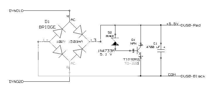
Here's a circuit I built. It's specifically for powering devices that can recharge themselves from a USB port, but that aren't bothered by the USB power going away when the dynohub stops turning.
Link to larger image
This is based on some ideas put forth by Steve K on the candlepower forum.
https://www.candlepowerforums.com/vb/.../t-174812.html
The circuit n4zou described earlier is really very inspired and elegant, I think. It provides a well regulated USB power output that stays up when the dynohub stops. On the other hand it needs intelligent manual intervention to keep its internal battery from overcharging. My circuit is simpler to operate because it pushes the battery management issues onto the rechargeable USB devices themselves.
I built a prototype for my son, who is getting ready for an extended bike tour. It seems to recharge his PDA very nicely from his Schmidt SON dynohub. We're hoping that it can also run a USB powered AA battery charger. I don't know how to predict which USB devices can tolerate intermittent power from the dynohub and occasional undervoltage at slow speeds. We'll just try out a few devices and see what works.
12-26-07, 11:06 AM
#10
Scott
Join Date: Jun 2006
Posts: 2,393
Bikes: Too Many
Mentioned: 0 Post(s)
Tagged: 0 Thread(s)
Quoted: 1 Post(s)
Likes: 0
Liked 1 Time
in
1 Post
My circuit eliminates that problem, the batteries act as voltage and current regulators and filter for clean power.
12-26-07, 01:07 PM
#11
Senior Member
Join Date: Jun 2005
Location: Spur TX
Posts: 1,991
Bikes: Schwinn folder; SixThreeZero EvryJourney
Mentioned: 0 Post(s)
Tagged: 0 Thread(s)
Quoted: 0 Post(s)
Likes: 0
Liked 0 Times
in
0 Posts
Son is a RAAM qualified cyclist, so overcharging is a definite possibility. It would be sweet to have your constant regulated output even on hills and during stops, though. I'll try putting 4 series connected NiMH cells in a battery holder directly across the output of my circuit and see what happens. The zener shunt should protect against the worst case fast overcharging. While Son is on tour he can cycle his batteries and rechargeable devices through the charger and adjust his average power consumption until he finds the optimum usage pattern.
12-27-07, 10:12 AM
#12
The Improbable Bulk
Join Date: Jul 2005
Location: Wilkes-Barre, PA
Posts: 8,379
Bikes: Many
Mentioned: 0 Post(s)
Tagged: 0 Thread(s)
Quoted: 5 Post(s)
Likes: 0
Liked 7 Times
in
7 Posts
I am not an electronics guy, but something similar to n4zou's circuit may be making it onto my bike.
I don't do much night riding, but I want to use some existing LED lights and a dynamo to power them, and provide a USB power connector as well.
I am typing this from work, and can't see the diagram... so the questions are based on my memory of the diagram, please feel free to correct me.
The front light I want to use is a Cateye Opticube that uses 4 AA batteries (I forget the model, but it is a couple of years old), and the tail light is a Cateye TL-LD1000 that uses 2 AAA batteries.
The questions (some I could answer by looking, but I would like to have information before I look to confirm I am seeing what I think I am seeing).
Are the batteries in the headlight likely to be in series?
In running wires to the LD-1000, what resister should I put on the circuit? Does it matter if the resistor is on the positive or negative side?
Can I rely on the front LED portion to just work with the existing switch as S2? (am I correct that the wires to the tail light could also be soldered after this switch)
Are there any issues with all of the circuitry being constructed within the headlight shell? Room? Heat dissipation? Other?
How about driving a Megahorn, which currently uses a 9 volt battery? My memory of the little bit of reading on electronics many years ago isn't sharp enough to remember how to increase voltage... or should I switch my plan to use 6 NiMH batteries, and step down for the headlight and USB?
I am looking forward to my first cycling electronic modification.
12-27-07, 12:44 PM
#13
Senior Member
Join Date: Jun 2005
Location: Spur TX
Posts: 1,991
Bikes: Schwinn folder; SixThreeZero EvryJourney
Mentioned: 0 Post(s)
Tagged: 0 Thread(s)
Quoted: 0 Post(s)
Likes: 0
Liked 0 Times
in
0 Posts
...Overcharging the 4 Ni-MH batteries is possible. I've found that in actual use this is not a big problem. When using just the LED headlight and LED taillight with just 120mA of recharging current and traveling anywhere other than an interstate highway (illegal to be on one on a bike in the USA) it's almost impossible to overcharge the batteries...
Link to larger image
I don't have personal engineering experience with NiMH cells, but I read that the newer batteries are designed to better tolerate a certain amount of overcharging at trickle currents. So the stern warnings we see about the dangers of trickle charging with NiMH might be somewhat overstated with respect to current NiMH cell designs. At least that is what I'm thinking right now.
If overcharging isn't a serious concern, n4zou's circuit might have an additional advantage. Its charging current is full wave rectified DC, which might amount to a pulse charging scheme. That is, it puts a pulse of charge into the cell and then briefly removes the charging current. The interval between charge pulses might allow better recovery from polarization effects. So maybe I'll try removing the 4700 uF filter capacitor in my circuit.
12-28-07, 10:27 AM
#14
Scott
Join Date: Jun 2006
Posts: 2,393
Bikes: Too Many
Mentioned: 0 Post(s)
Tagged: 0 Thread(s)
Quoted: 1 Post(s)
Likes: 0
Liked 1 Time
in
1 Post
I am not an electronics guy, but something similar to n4zou's circuit may be making it onto my bike.
I don't do much night riding, but I want to use some existing LED lights and a dynamo to power them, and provide a USB power connector as well.
I am typing this from work, and can't see the diagram... so the questions are based on my memory of the diagram, please feel free to correct me.
The front light I want to use is a Cateye Opticube that uses 4 AA batteries (I forget the model, but it is a couple of years old), and the tail light is a Cateye TL-LD1000 that uses 2 AAA batteries.
The questions (some I could answer by looking, but I would like to have information before I look to confirm I am seeing what I think I am seeing).
Are the batteries in the headlight likely to be in series?
How about driving a Megahorn, which currently uses a 9 volt battery? My memory of the little bit of reading on electronics many years ago isn't sharp enough to remember how to increase voltage... or should I switch my plan to use 6 NiMH batteries, and step down for the headlight and USB?
12-29-07, 10:14 PM
#16
deep stuff
Join Date: Jun 2007
Location: Nampa, ID
Posts: 250
Bikes: Road, Touring, Mountain Bike
Mentioned: 0 Post(s)
Tagged: 0 Thread(s)
Quoted: 0 Post(s)
Likes: 0
Liked 0 Times
in
0 Posts
It actually is very legal to bike on much of the US interstate system that is outside of cities. RAAM even uses Interstate 10 which I've also traveled on trips. Here in Idaho I 84 is much traveled by bikes outside of metropolitan areas. There may be no alternative to using the interstates, that is why it's legal.
Bruce
WB5GZT
12-30-07, 10:20 AM
#17
Scott
Join Date: Jun 2006
Posts: 2,393
Bikes: Too Many
Mentioned: 0 Post(s)
Tagged: 0 Thread(s)
Quoted: 1 Post(s)
Likes: 0
Liked 1 Time
in
1 Post
Scott
It actually is very legal to bike on much of the US interstate system that is outside of cities. RAAM even uses Interstate 10 which I've also traveled on trips. Here in Idaho I 84 is much traveled by bikes outside of metropolitan areas. There may be no alternative to using the interstates, that is why it's legal.
Bruce
WB5GZT
Every few years special interest groups try to get the state to build paths for non motorized and motorized devices that cant exceed 20 mph beside the interstate highways but as these vehicles or walkers don't use fuel or so very little of it they don't pay enough in road taxes to build and maintain the highway systems. Therefor it's not in the the government's interest to build them.
01-03-08, 10:14 PM
#18
Senior Member
Join Date: Jun 2005
Location: Spur TX
Posts: 1,991
Bikes: Schwinn folder; SixThreeZero EvryJourney
Mentioned: 0 Post(s)
Tagged: 0 Thread(s)
Quoted: 0 Post(s)
Likes: 0
Liked 0 Times
in
0 Posts
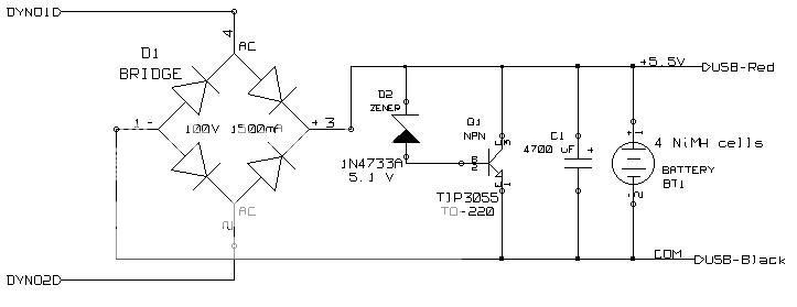
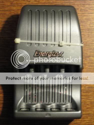
Here's the dynohub powered USB charger prototype I built. I gutted an Energizer brand 15-minute charger (model CH15MNCP4). It's expensive but it has a nice holder for 4 AA or AAA NiMH cells and contains a treasure trove of parts for the junk box.
When connected to the dynohub, the 4 NiMH cells are recharged. Output power is available at the USB connector while the batteries are charging, or the dynohub can be disconnected to use the charger as a portable USB power pack in camp.
I think the batteries could also be charged simply by plugging the charger into a USB connector at for example an internet cafe. You won't get a full charge in an hour of course, but an hour's worth of charging in an internet cafe saves an hour of charging with the dynohub, which might be worthwhile.
The circuit is the one in post #13 of this thread, with the 4700 uF filter capacitor omitted.
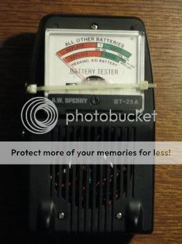
I added a panel meter to the back of the charger to show the voltage of the battery pack. I got the panel meter from an old analog battery tester, by cutting it out from the plastic case. All analog panel meters are really milliammeters. I determined my meter was 0.25 mA full scale. The meter face was marked with a green range labelled GOOD and a red range labelled REPLACE. Instead of trying to relabel the meter, I added a string of LEDs and diodes to drop the voltage and also a 10K pot to adjust the meter range so that the green and red markings on the meter indicate the battery is more than half charged (green range) or less than half charged (red range).
Here you can see the spring loaded holder for 4 NiMH batteries, either AA or AAA size:
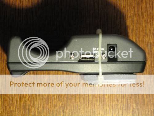
Side view. The power connector goes to either a dynohub, or alternatively a DC power supply (6-12 VDC). The USB connector is next to the power connector:
This is the bottom view, showing the battery voltage meter:
Besides the obvious mechanical deficiencies, another problem with the circuit is that when the dynohub is disconnected, the batteries drain at about 25 mA through the power transistor. For now the batteries can be removed when the charger isn't being used. I'll have to experiment with ways to eliminate the unwanted 25 mA current drain.
When connected to the dynohub, the 4 NiMH cells are recharged. Output power is available at the USB connector while the batteries are charging, or the dynohub can be disconnected to use the charger as a portable USB power pack in camp.
I think the batteries could also be charged simply by plugging the charger into a USB connector at for example an internet cafe. You won't get a full charge in an hour of course, but an hour's worth of charging in an internet cafe saves an hour of charging with the dynohub, which might be worthwhile.
The circuit is the one in post #13 of this thread, with the 4700 uF filter capacitor omitted.
I added a panel meter to the back of the charger to show the voltage of the battery pack. I got the panel meter from an old analog battery tester, by cutting it out from the plastic case. All analog panel meters are really milliammeters. I determined my meter was 0.25 mA full scale. The meter face was marked with a green range labelled GOOD and a red range labelled REPLACE. Instead of trying to relabel the meter, I added a string of LEDs and diodes to drop the voltage and also a 10K pot to adjust the meter range so that the green and red markings on the meter indicate the battery is more than half charged (green range) or less than half charged (red range).
Here you can see the spring loaded holder for 4 NiMH batteries, either AA or AAA size:
Side view. The power connector goes to either a dynohub, or alternatively a DC power supply (6-12 VDC). The USB connector is next to the power connector:
This is the bottom view, showing the battery voltage meter:
Besides the obvious mechanical deficiencies, another problem with the circuit is that when the dynohub is disconnected, the batteries drain at about 25 mA through the power transistor. For now the batteries can be removed when the charger isn't being used. I'll have to experiment with ways to eliminate the unwanted 25 mA current drain.
01-04-08, 07:13 AM
#19
Senior Member

Join Date: Aug 2003
Location: arlington, VA
Posts: 1,764
Mentioned: 0 Post(s)
Tagged: 0 Thread(s)
Quoted: 6 Post(s)
Likes: 0
Liked 5 Times
in
4 Posts
Yes! That�s exactly what I am doing. Without the batteries the voltage developed by the dynamo can easily exceed 6-volts according to the load. Another thing to remember is the dynamo is going to make 500mA of current and if the device your powering uses less than 500mA you can easily burn up that device. The batteries will load the dynamo keeping the battery voltage regulated to the battery packs rated voltage. The way this works is as the voltage generated by the dynamo approaches the rated voltage of the batteries the batteries will place a high enough load on the dynamo shorting it out preventing higher voltage. If the device connected to the batteries draws less than 500mA the batteries will absorb the excess current using it for recharging. If your device draws just a few milliamps of current you'll need to be careful not to overcharge the batteries. The more current drawn by the device the more time it will take to recharge the batteries. Nearly all devices designed to be powered by a USB port draw less than 500mA of current.
When I am running my lights with the dynamo connected I have 120mA of excess current recharging the batteries. If I am not stopping very much I disengage my dynamo for 15 minutes of every hour of riding to prevent overcharging.
Set your digital multimeter to read current making sure it is set to read up to 500mA of current. Connect the red positive meter lead to the positive post of the batteries. Connect the black meter lead to the positive side of the circuit where the positive post of the batteries would be connected. Turn on your device or lights so you can read the current being used by the device. Start riding watching the meter (and where your going). As you ride faster you will note current draw decreasing and at some point you will start to see excess current causing a positive reading on the meter. At this point you're recharging the batteries! Note this speed on your Cyclocomputer. Ride faster and note the speed where the current stops increasing. This is the point where the dynamo saturates and cannot produce more current. Note this speed, as this is the maximum recharging current for your batteries and the device being powered by your dynamo. Calculate how much time you can disengage your dynamo per hour to prevent overcharging the batteries. You can also use the battery meter in the device to indicate when to disengage the dynamo and dynamo batteries from the device when it shows fully recharged.
Another option to prevent overcharging would be to put a switch in series with one of the diodes to switch the bridge to half wave mode at higher speed thereby halving output.
Seems a charge level circuit with an led indicator could be used to let you know you've got the battery charged, then manually flip the charge circuit off.
01-08-08, 03:41 AM
#20
Senior Member
Join Date: Jun 2005
Location: Spur TX
Posts: 1,991
Bikes: Schwinn folder; SixThreeZero EvryJourney
Mentioned: 0 Post(s)
Tagged: 0 Thread(s)
Quoted: 0 Post(s)
Likes: 0
Liked 0 Times
in
0 Posts
Okay, I now have some practical experience with my zener regulated USB charger. The bottom line is that n4zou's design is simpler and more efficient. I was unable to pick a single fixed zener voltage that would efficiently charge the batteries and at the same time prevent overcharging.
That is, if you select a zener voltage that's high enough to allow efficient battery charging, it won't be low enough to prevent overcharging. Therefore, it really accomplished nothing of benefit to have a zener regulator at all, since the batteries do a very fine job of regulating (up to the point where they are overcharged).
That is, if you select a zener voltage that's high enough to allow efficient battery charging, it won't be low enough to prevent overcharging. Therefore, it really accomplished nothing of benefit to have a zener regulator at all, since the batteries do a very fine job of regulating (up to the point where they are overcharged).
01-08-08, 06:25 AM
#21
Formerly Known as Newbie

Join Date: Mar 2002
Location: Helsinki, Finland
Posts: 6,249
Mentioned: 1 Post(s)
Tagged: 0 Thread(s)
Quoted: 2 Post(s)
Likes: 0
Liked 4 Times
in
3 Posts
I have an evil plan of asking an electronically-inclined friend to get the parts and do the work for me. I've helped him with other things. It would be fun and useful to learn this myself, but right now I don't have that time available. And, it might be a good idea to practise on something else first, before attempting to put this together.
Thank you n4zou and Platy for posting your designs.
--J
__________________
To err is human. To moo is bovine.
Who is this General Failure anyway, and why is he reading my drive?
Become a Registered Member in Bike Forums
Community guidelines
To err is human. To moo is bovine.
Who is this General Failure anyway, and why is he reading my drive?
Become a Registered Member in Bike Forums
Community guidelines
01-08-08, 12:01 PM
#22
Scott
Join Date: Jun 2006
Posts: 2,393
Bikes: Too Many
Mentioned: 0 Post(s)
Tagged: 0 Thread(s)
Quoted: 1 Post(s)
Likes: 0
Liked 1 Time
in
1 Post
Okay, I now have some practical experience with my zener regulated USB charger. The bottom line is that n4zou's design is simpler and more efficient. I was unable to pick a single fixed zener voltage that would efficiently charge the batteries and at the same time prevent overcharging.
That is, if you select a zener voltage that's high enough to allow efficient battery charging, it won't be low enough to prevent overcharging. Therefore, it really accomplished nothing of benefit to have a zener regulator at all, since the batteries do a very fine job of regulating (up to the point where they are overcharged).
That is, if you select a zener voltage that's high enough to allow efficient battery charging, it won't be low enough to prevent overcharging. Therefore, it really accomplished nothing of benefit to have a zener regulator at all, since the batteries do a very fine job of regulating (up to the point where they are overcharged).
12-28-09, 10:10 AM
#23
Newbie
Join Date: Dec 2009
Posts: 3
Mentioned: 0 Post(s)
Tagged: 0 Thread(s)
Quoted: 0 Post(s)
Likes: 0
Liked 0 Times
in
0 Posts
Hi there,
I've just tried making a USB charger for my dynohub. I'm using a shimano 3N80 hub, 6volts, 3 watts.
I used this exact diagram https://www.bikeforums.net/showthread...ht=usb+charger
It charges my old 1st generation ipod nano but won't charge my 6th generation 120G ipod classic.
Can anyone confirm that this charger will work on the 6th Gen. 120G ipod classic
12-28-09, 05:59 PM
#25
Newbie
Join Date: Dec 2009
Posts: 3
Mentioned: 0 Post(s)
Tagged: 0 Thread(s)
Quoted: 0 Post(s)
Likes: 0
Liked 0 Times
in
0 Posts
zzyzy_xyzzy is there anyway to trigger the digital controller on the USB port to get tthe ipod to charge?
I just tried the charger on a 5th Gen iPod and it works. It seems to be just th 6th Gen iPod that won't charge. It's a shame that's the one i need to work!
I just tried the charger on a 5th Gen iPod and it works. It seems to be just th 6th Gen iPod that won't charge. It's a shame that's the one i need to work!

