Hey Everybody,
I built my first frame last winter and I loved it! I used a pretty horrendous set of hacked together jig from an aluminum L bracket and some maple tubing clamps. The bikes rides pretty well, but it ended up being tweaked by about 1 degree HT to ST wise and the rear dropouts aren't aligned very well. So, I want to make more frames and better! I'm thinking a nice jig might make the process of building more frames faster and more enjoyable.
Anyway, I've started to design a jig and I was hoping to hear what you guys think of the design to see if there are some flaws or omissions. I'm doing the design in Solid Works and these are screen caps. I haven't got around to putting in the hardware, or all the collars or tube blocks, but I think there is enough here to get an idea of how it will work. The extrusions are 8020 brand aluminum and the flat parts are going to be water jet cut.
The primary purpose of this jig is to build fillet brazed or lugged track, road, and touring frames. My goal is to make a jig that is inexpensive by using simple parts and versatile enough to do 48-64cm frames.
Image One
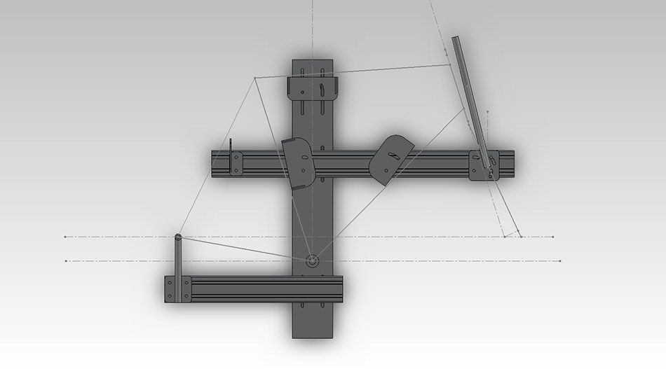
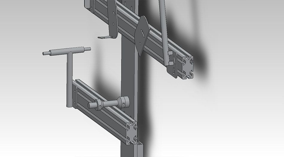
Image Two

So, the general idea is similar to the henry james jig with collars securing the BB and head tube (head tube collars not pictured). The 8020 extrusions slide horizontally along their channels and then vertically in slotted holes in the main vertical plate. The HT shaft rotates on the extrusion it is mounted to with a 60-78 degree HT angle range. The tubes are supported on V blocks with wire securing them to the blocks.
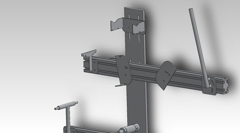
Detail of the V block type setup. The plate can slide vertically and rotate to accommodate traditional or compact geometry. I plan to wrap wire around the tube and block to hold it securely at the correct angle, but the tube will be able to shift along it's long axis: Good or bad idea?

Detail of the BB mount and rear dropout holder. The BB is held in place with cones that fit around a 3/4" shaft. The cones are secured in place with one 7mm set screw: Do you guys think this will be secure enough or do the cones need to clamp onto the shaft like they do on the henry james jig? I plan to put a spacer behind the BB cones to center it along the main building plane. Alternate spacers could be used to different BB shell widths.
The rear dropout holder will have a lip for 120mm dropouts, and I plan to have spacers made for 130mm dropout spacing. I was thinking of using threaded studs coming out of the holder (threads not shown in image) and then securing the dropouts with nuts on the outside. The BB drop can be adjusted by sliding the extrusion up or down.
BB Shell mock-up in place

The rear has a 3" long section of 1.5" square tube to accommodate some sort of square tube mount. You can see the slotted holes here.
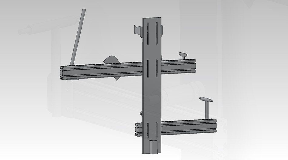
My plan is to use a T shaped rest to help position the seat stays. It can slide horizontally to accommodate different frame sizes.
Any feedback would be greatly appreciated. Remember there are a couple V blocks missing from the images, and the HT collars are not present as well. I'll post updated images as the design progresses and things will start to look pretty realistic.
Also if anyone is interested in getting a jig I will be able to get better pricing on the machined/water jet cut parts if I get more than one set built! I could put together a McMaster Carr order list to go with the machined parts if anyone is interested in building one of these jigs. I'm just wanting to do frame building as a hobby, so it would be nice to get the price down on these parts. I'm not sure how much the parts here will cost, but hopefully it will be below $1000usd. I'd be happy to share the 3D files too if anyone has a friend with a machine shop and wants to build a jig.