And, going even further off the deep end, I decided to teach myself how to do Finite Element Analysis to evaluate the strength of the FSD I built (and where I could get away with removing material to lighten it.
The problem was that not only am I not a mechanical engineer, but I've never done a Finite Element Analysis in my life. But fortunately we live in the age of free Open Source software packages and abundant YouTube tutorials. Who needs a fancy degree when you can watch videos for a week and fake it. So I downloaded FreeCad and taught myself just enough to design parts and model stresses. Here are some results:
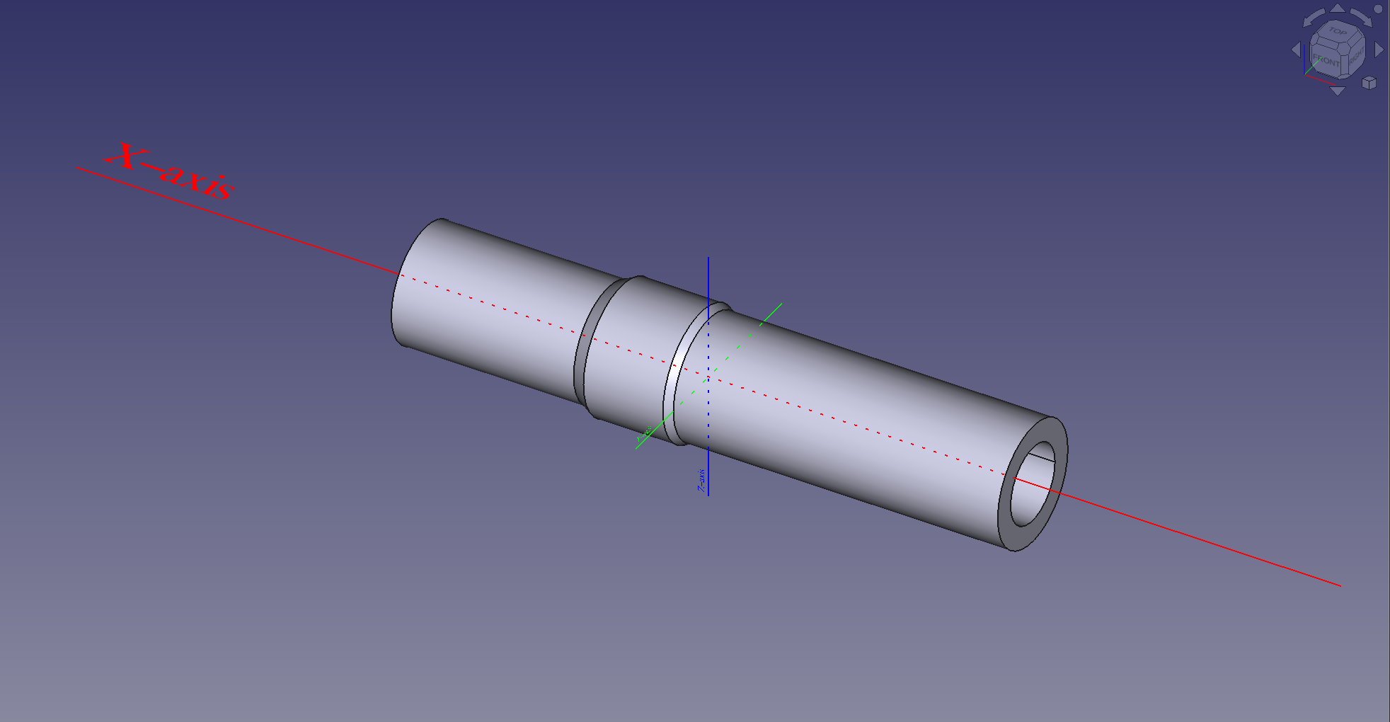
My initial design was basically a 150mm cylinder of 7075 Aluminum, 28.6mm in diameter on the upper 45mm where the stem mounts and 30mm in diameter on the lower 80mm where it mounts in the Future Shock compatible head set. Finally, and rather arbitrarily I bored a 3/4" hole down the center as shown:
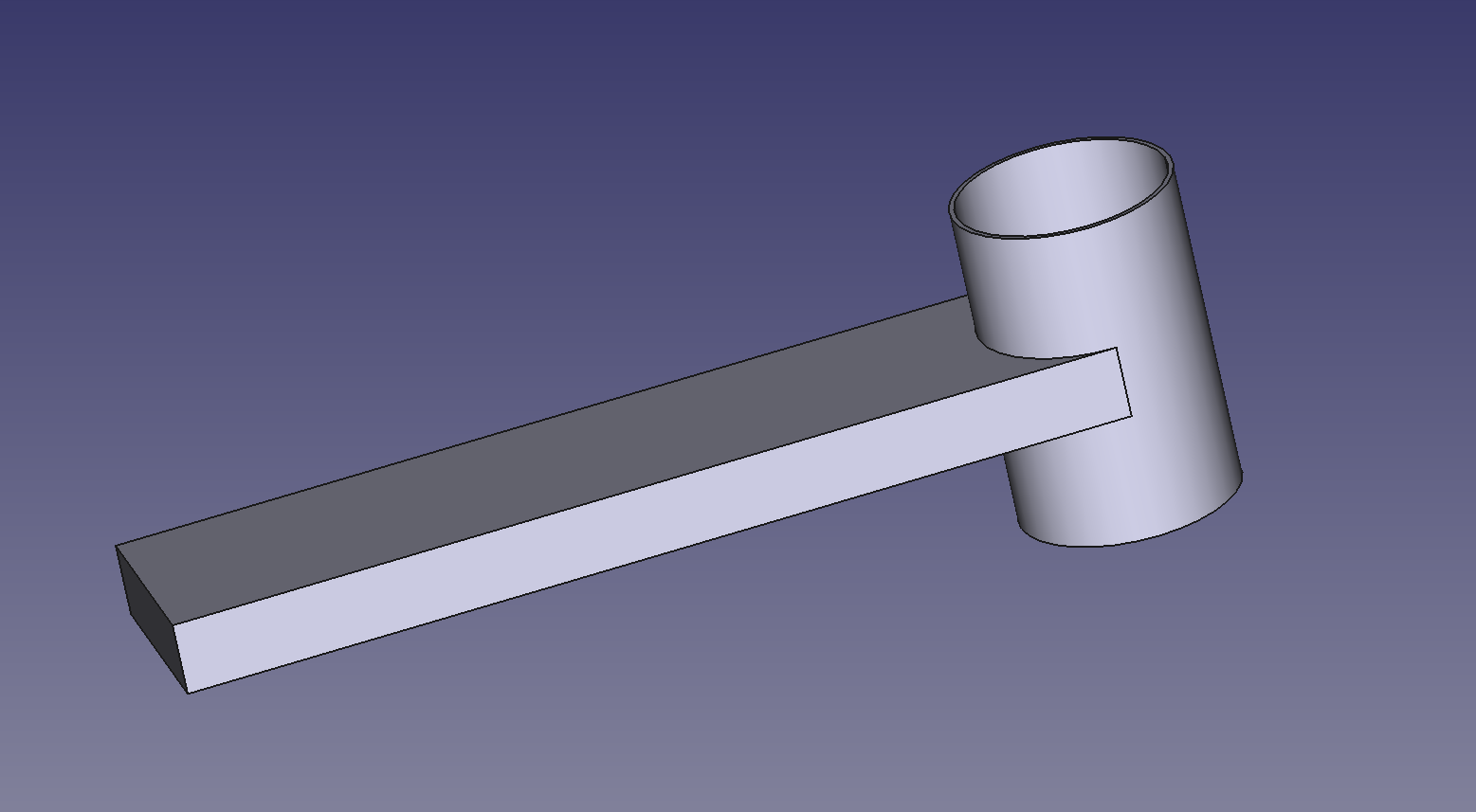
To test how strong this thing was I first had to model a stem and headset that it would mount to. The stem I came up with was a simple plank and sleeve as shown:
and the headset I modeled as just a fixed cylinder. Putting everything together the model looked like this:
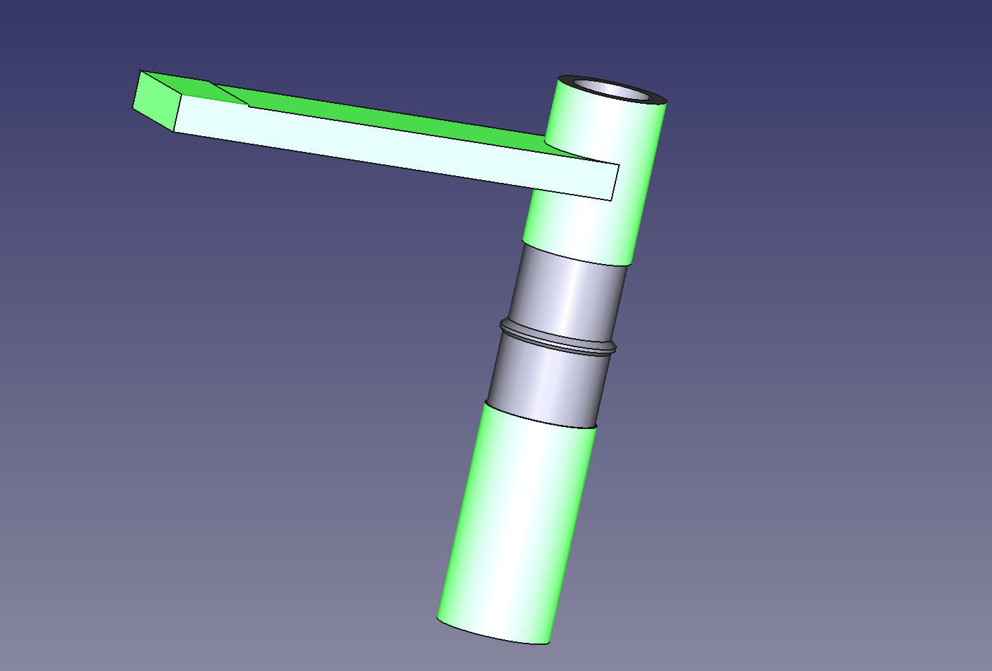
with the stem and headset highlighted here in green and the free-to-flex FSD in between. The final bit is to set test conditions. In this case I held the headset fixed. Allowed to the stem to move, but only as a rigid body and applied a force of 400lb 120mm from the center axis of the FSD. Why 400lb and 120mm? They're both a lot more than the FSD will see in real life and most importantly, they were the test conditions that the Bike Sauce used, so at least it would give me a semi-valid point of comparison.
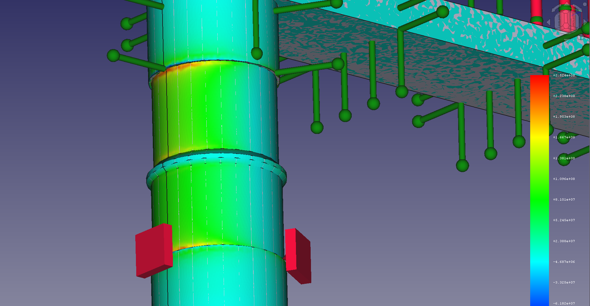
Anyway, with all these boundary conditions set it's pretty straightforward to get FreeCad to spit out a map of the stresses on the part. This ends up looking like:
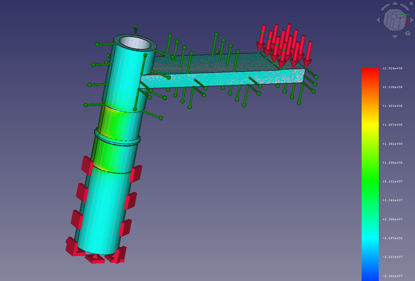
with all the squares, arrows and rods representing the boundary conditions on the headset and stem described above.
Now the key feature - where is the stress highest? Looking closely we see (perhaps unsurprisingly) that stress is maximized right at the sharp edges where the FSD is clamped. Here's a closeup - those red rings are the likely failure points if the load limits are exceeded.
Well this is getting long winded. The next step is varying the design to see how the stresses change, choosing an optimum and then actually building the thing in my shop. Save that for the next post.