


Alfine 11 shift spring assembly
 10-14-23 | 10:24 PM
#1
Thread Starter
Newbie

Joined: Oct 2010
Posts: 69
Likes: 3
From: New Zealand
Bikes: Bikes are just like shoes, make sure you have the right ones for the right occasion
Alfine 11 shift spring assembly
I have unfortunately managed to go where I know I should not. I've accidentally dismantled the shifting assembly that sits on the right side of the Alfine 11 axle assembly and now need to get it all back together.
Despite numerous google searches I have yet to find a fool proof way of get this to work, so I'm starting this thread, both to see if someone who has actually-been-there-before can help, and also to document the steps I try in case I succeed and other folk want to follow along with how it is done.
NB: I found some excellent documentation for the Alfine 8 hub. The 11 speed is sufficiently different that a different approach is reuired.
https://rideyourbike.com/shimano8axl...drawings.shtml
Last edited by fastbike; 10-14-23 at 11:38 PM.
 10-14-23 | 10:30 PM
#2
Thread Starter
Newbie
Joined: Oct 2010
Posts: 69
Likes: 3
From: New Zealand
Bikes: Bikes are just like shoes, make sure you have the right ones for the right occasion
Here's the part as it should look before being fitted with all the other parts and placed back into the shell. BTW, that job is the easy part.

10-14-23 | 11:08 PM
#3
Thread Starter
Newbie
Joined: Oct 2010
Posts: 69
Likes: 3
From: New Zealand
Bikes: Bikes are just like shoes, make sure you have the right ones for the right occasion
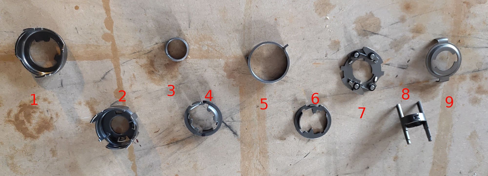
And here's a shot of the dismantled parts sitting on my work bench. I've numbered them so I can refer to the parts as this thread progresses.
1 Keeper. This is keyed to the axle and holds all the parts in alignment.
2 Shift Cage. This fits inside of the keeper and is keyed onto the actuator arm that rotates about the axle and depresses/releases the sun pinion pawls. You can see that the are two internal tabs that are pressed into the base along with a cutout for keying to the actuator arm. There is also a torsion "override" spring with a hook at each end fitted inside the cage. The inner hook of the spring abuts one of the tabs, the outer hook keys into part #4. The purpose of this spring is to allow a shift to be started even if the hub is under pressure and cannot execute the shift until pressure is released (e.g. at top dead centre when pedalling pressure is reduced). In theory the spring could be rotated around so the hook sits on the other tab, or the protrusion of the actuator arm, but you will see later on that it needs to be as shown in order to correctly orientate the parts - I figured this out via trial and observation.
3 Spacing Bush. This has a small notch that should face into the centre and be set over the hook of the override spring. The outer hook can be manipulated with a screwdriver so this bush can be pressed down firmly.
4 Inner Spring Cage. This has a protrusion with a notch to hook the spring from part #2. On the other side it has a protrusion with a notch to grab the lower hook of the shift spring (#5), along with two keyed notches to fit with the drive key (#8). It can only fit one way, the notches need to be facing out.
5. Shift Spring. This torsion spring supplies tension to the shifting cable. There are two outward facing hooks, one slightly longer than the other.
6. Outer Spring Cage. This is keyed to grooves in the axle to prevent it from rotating, along with a hook that needs to face the shift spring so that the spring can be tensioned correctly.
7. Clutch. This shifts the gearset between the upper and lower ranges.
8. Drive Key. This rotates the Shift Cage and the outside end is keyed to the driver for the shifting pulley.
9. Pawl Tripper. This triggers the clutch.
Parts on workbench
10-14-23 | 11:20 PM
#4
Thread Starter
Newbie
Joined: Oct 2010
Posts: 69
Likes: 3
From: New Zealand
Bikes: Bikes are just like shoes, make sure you have the right ones for the right occasion
Here a close up of part #2 (Shift Cage) showing the override spring hooked into the tab

And here's a picture showing part #4 (Inner spring cage): the red notches key to the drive key (#8), the green picks up the hook from the override key, and the blue has the hook from the shift spring (#5)

And here's a picture showing part #4 (Inner spring cage): the red notches key to the drive key (#8), the green picks up the hook from the override key, and the blue has the hook from the shift spring (#5)
10-14-23 | 11:33 PM
#5
Thread Starter
Newbie
Joined: Oct 2010
Posts: 69
Likes: 3
From: New Zealand
Bikes: Bikes are just like shoes, make sure you have the right ones for the right occasion
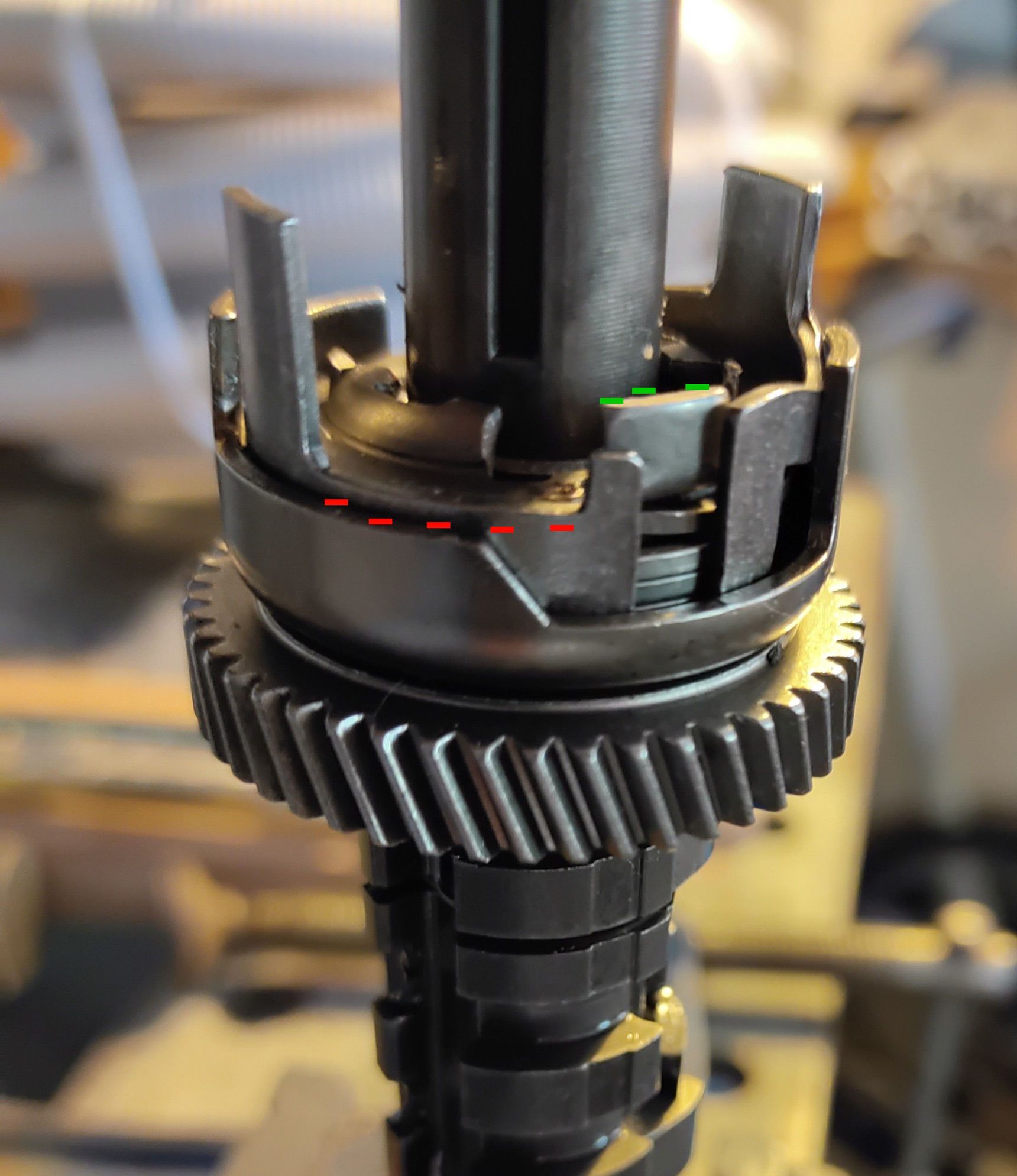
Here's s photo of the first 4 parts fitted to the axle. This all relatively straight forward. The red marks show the lowered cutout on the Shift Cage (#2) to allow the outward facing hook to be caught by the upstand to the right of these marks. The part marked in green is the inner spring cage (#4) - which will rotate CW against the override spring if the shift is impeded, if which case the green upstand will engage with the shift spring.
Fitting the shift spring is the next part of the puzzle. There are two isues to be resoled.
First, one hook is longer than the other - does the longer hook fit facing the axle centre in which case is it long enough to contact both the shift cage and the inner spring cage ? Or does the shorter hook fit here to provide rotational clearance.
Some experimentation is in order.
Second, how far does this spring need to be rotated to provide sufficient tension to the shifting cable. And how to do this while attempting to fit the upper spring cage to capture the tensioned spring. Note that the upper spring cage cannot rotate as it is keyed to the axle so I can't hook the spring to the cage and wind it up.
This is the part I'm struggling with, so I'm really looking for some guidance from folk who have attempted this before. Otherwise I think I'll need to make some type of fitting jig to wind the spring up, clamp it in the tensioned state, and then fit it without letting go of the tension !
10-15-23 | 10:53 AM
#6

Senior member


Joined: Oct 2004
Posts: 8,368
Likes: 889
From: Oakville Ontario
I have not overhauled this assembly on an 11 speed but I have done a few 8 speeds. Should be fairly similar but note that the 11 speed spring will be wound in the opposite direction to the one in this video.
11-17-23 | 11:14 PM
#7
Thread Starter
Newbie
Joined: Oct 2010
Posts: 69
Likes: 3
From: New Zealand
Bikes: Bikes are just like shoes, make sure you have the right ones for the right occasion
Thanks Dan, the mechanism is sufficiently different that an entirely novel technique is required.
Start by holding the axle in a vice with soft jaws.
Fit the first 4 parts to the axle ensuring #4 (inner spring cage) is rotated as far clockwise as possible so it engages the spring in #2 underneath.
Using some thin (less than 1.0mm) malleable copper wire bind the shift spring #5 to the outer cage #6 so this can be manipulated without it pinging apart. The shorter hook on this shift spring should be free (the longer hook latches into #6). This is a temporary arrangement and will be removed later so use only a simple loop and twist it with pliers to hold the two parts together.
While holding the lower hook of the spring with some fine needle nose pliers (ideally locking) drop this assembly onto the axle. It has tabs that fit into grooves in the axle so can go in one of 2 positions. Fit it so that the spring will be tensioned around 270 degrees in the next step.
As you slide the assembly down the axle, pull the lower hook of the spring around clockwise until it is past the notch in #4 and carefully latch it into place. You'll need a firm grip on the pliers if they're not locking as the spring hook will want to do its own thing. Press the outer cage #6 firmly onto the axle.
Remove the copper binding wire.
The next part is a little tricky as you need to manipulate part #4 clockwise while not upsetting the spring and plate you just fitted. Some small flat bladed screw drivers are useful but you need to end up tensioning the inner spring cage #4 against the spring in the shift cage #2 about 15 degrees so the drive key #8 will drop in after the next step. I used two screwdrivers, the first I used to manipulate #4 by poking it in the gap between the axle and #6 and levering part #4 around until I could get another screw driver , inserted from the side between the tab on #4 and the upstand on part #2. I then temporary fitted the drive key and using a shifting spanner rotated the key clockwise about 20 degrees until the the tab on part #4 moved past the upstand on part #2. I then wedged a small screwdriver to hold it in position for the next step and removed the drive key.
Fit the clutch onto the axle ensuring the slots at the perimeter fit over the tabs of the shift cage.
Now fit the drive key #8 - it should be rotated anti clockwise and fit down against the clutch with no gap. You may need to fettle around if the spring is not providing sufficient clearance against the axle to get it seated.
Remove screw drivers etc
Finally fit the tripper #9.
Last edited by fastbike; 11-18-23 at 04:31 AM.
04-13-25 | 12:02 AM
#8
Newbie
Joined: Apr 2025
Posts: 1
Likes: 0
From: Colorado
thank you Fastbike and Dan for sharing your experience and knowledge with the community. I believe Fastbikes writeup on spring assembly for Alfine 11 is the only resource out there.
I had to replace my clutch ring which I delayed several years due to fears of dislodging the spring assembly. And when I finally set out to do it I did mess up the spring assembly.. I took some photos while reassembling it but forum won't allow me to upload anything until I hit min 10 posts..
anyway, after replacing clutch ring and putting everything back together for maybe 10 times I have my wheel in place but gear shifting does not seem right. I believe I am missing upper gears (7 through 11). After switching from 6 to 7 it feels like I am in 1st or 2nd again, which would probably mean that clutch is not binding?
I have not ridden my bike under heavy load but there is sufficient amount of lubrication and cable is aligned with yellow marks (on gear 6). Shifting itself works good, no weird or grinding feel to it.
I am trying to troubleshoot and see what can be done. Only thing that I did differently vs Fastbike's notes is hooked override spring on the protrusion from actuator which is how I found the spring while I was taking everything off. This would lead to slightly tighter preload on override spring but I am having hard time convincing myself whether that could lead to symptoms that I am experiencing.
Any insights are appreciated as my next course of action is to give in and buy replacement axle with spring assembly.
04-13-25 | 07:28 AM
#9
Full Member

Joined: Dec 2015
Posts: 369
Likes: 76
Thanks Dan, the mechanism is sufficiently different that an entirely novel technique is required.
Start by holding the axle in a vice with soft jaws.
Fit the first 4 parts to the axle ensuring #4 (inner spring cage) is rotated as far clockwise as possible so it engages the spring in #2 underneath.
Using some thin (less than 1.0mm) malleable copper wire bind the shift spring #5 to the outer cage #6 so this can be manipulated without it pinging apart. The shorter hook on this shift spring should be free (the longer hook latches into #6). This is a temporary arrangement and will be removed later so use only a simple loop and twist it with pliers to hold the two parts together.
While holding the lower hook of the spring with some fine needle nose pliers (ideally locking) drop this assembly onto the axle. It has tabs that fit into grooves in the axle so can go in one of 2 positions. Fit it so that the spring will be tensioned around 270 degrees in the next step.
As you slide the assembly down the axle, pull the lower hook of the spring around clockwise until it is past the notch in #4 and carefully latch it into place. You'll need a firm grip on the pliers if they're not locking as the spring hook will want to do its own thing. Press the outer cage #6 firmly onto the axle.
Remove the copper binding wire.
The next part is a little tricky as you need to manipulate part #4 clockwise while not upsetting the spring and plate you just fitted. Some small flat bladed screw drivers are useful but you need to end up tensioning the inner spring cage #4 against the spring in the shift cage #2 about 15 degrees so the drive key #8 will drop in after the next step. I used two screwdrivers, the first I used to manipulate #4 by poking it in the gap between the axle and #6 and levering part #4 around until I could get another screw driver , inserted from the side between the tab on #4 and the upstand on part #2. I then temporary fitted the drive key and using a shifting spanner rotated the key clockwise about 20 degrees until the the tab on part #4 moved past the upstand on part #2. I then wedged a small screwdriver to hold it in position for the next step and removed the drive key.
Fit the clutch onto the axle ensuring the slots at the perimeter fit over the tabs of the shift cage.
Now fit the drive key #8 - it should be rotated anti clockwise and fit down against the clutch with no gap. You may need to fettle around if the spring is not providing sufficient clearance against the axle to get it seated.
Remove screw drivers etc
Finally fit the tripper #9.
Start by holding the axle in a vice with soft jaws.
Fit the first 4 parts to the axle ensuring #4 (inner spring cage) is rotated as far clockwise as possible so it engages the spring in #2 underneath.
Using some thin (less than 1.0mm) malleable copper wire bind the shift spring #5 to the outer cage #6 so this can be manipulated without it pinging apart. The shorter hook on this shift spring should be free (the longer hook latches into #6). This is a temporary arrangement and will be removed later so use only a simple loop and twist it with pliers to hold the two parts together.
While holding the lower hook of the spring with some fine needle nose pliers (ideally locking) drop this assembly onto the axle. It has tabs that fit into grooves in the axle so can go in one of 2 positions. Fit it so that the spring will be tensioned around 270 degrees in the next step.
As you slide the assembly down the axle, pull the lower hook of the spring around clockwise until it is past the notch in #4 and carefully latch it into place. You'll need a firm grip on the pliers if they're not locking as the spring hook will want to do its own thing. Press the outer cage #6 firmly onto the axle.
Remove the copper binding wire.
The next part is a little tricky as you need to manipulate part #4 clockwise while not upsetting the spring and plate you just fitted. Some small flat bladed screw drivers are useful but you need to end up tensioning the inner spring cage #4 against the spring in the shift cage #2 about 15 degrees so the drive key #8 will drop in after the next step. I used two screwdrivers, the first I used to manipulate #4 by poking it in the gap between the axle and #6 and levering part #4 around until I could get another screw driver , inserted from the side between the tab on #4 and the upstand on part #2. I then temporary fitted the drive key and using a shifting spanner rotated the key clockwise about 20 degrees until the the tab on part #4 moved past the upstand on part #2. I then wedged a small screwdriver to hold it in position for the next step and removed the drive key.
Fit the clutch onto the axle ensuring the slots at the perimeter fit over the tabs of the shift cage.
Now fit the drive key #8 - it should be rotated anti clockwise and fit down against the clutch with no gap. You may need to fettle around if the spring is not providing sufficient clearance against the axle to get it seated.
Remove screw drivers etc
Finally fit the tripper #9.
04-13-25 | 06:42 PM
#10
Thread Starter
Newbie
Joined: Oct 2010
Posts: 69
Likes: 3
From: New Zealand
Bikes: Bikes are just like shoes, make sure you have the right ones for the right occasion
04-15-25 | 12:13 PM
#11
Full Member
Joined: Dec 2015
Posts: 369
Likes: 76
Dan posted a video showing how to reassemble an 8 speed neuxs axle. Your post after his said "this one requires a different procedure". In my experience the assembly for 8 and what you are working on are the same, at least for the axle.
04-20-25 | 06:51 PM
#12
Thread Starter
Newbie
Joined: Oct 2010
Posts: 69
Likes: 3
From: New Zealand
Bikes: Bikes are just like shoes, make sure you have the right ones for the right occasion
Yawn. The Alfine 8 and 11 are completely different. Have a good day, rather than trying to have the last word.
04-20-25 | 09:01 PM
#13
Senior Member

Joined: Sep 2004
Posts: 3,307
Likes: 1,048
From: Chicago area
Bikes: Airborne "Carpe Diem", Motobecane "Mirage", Trek 6000, Strida 2, Dahon "Helios XL", Dahon "Mu XL", Tern "Verge S11i"

