


Help wiring ebike controller
 09-25-24 | 10:37 AM
#1

Thread Starter
Newbie
Joined: Sep 2024
Posts: 22
Likes: 1
Help wiring ebike controller
I was given an ebike minus a battery. The controller isn’t wired up, and I don’t have a diagram. I’ve heard you can smoke these controllers if you’re not careful wiring them. I’m hoping somebody might be able to recognize this controller or is smarter than I am and just know what they are. I can’t post pictures until I have at least ten posts so I’ll describe them.
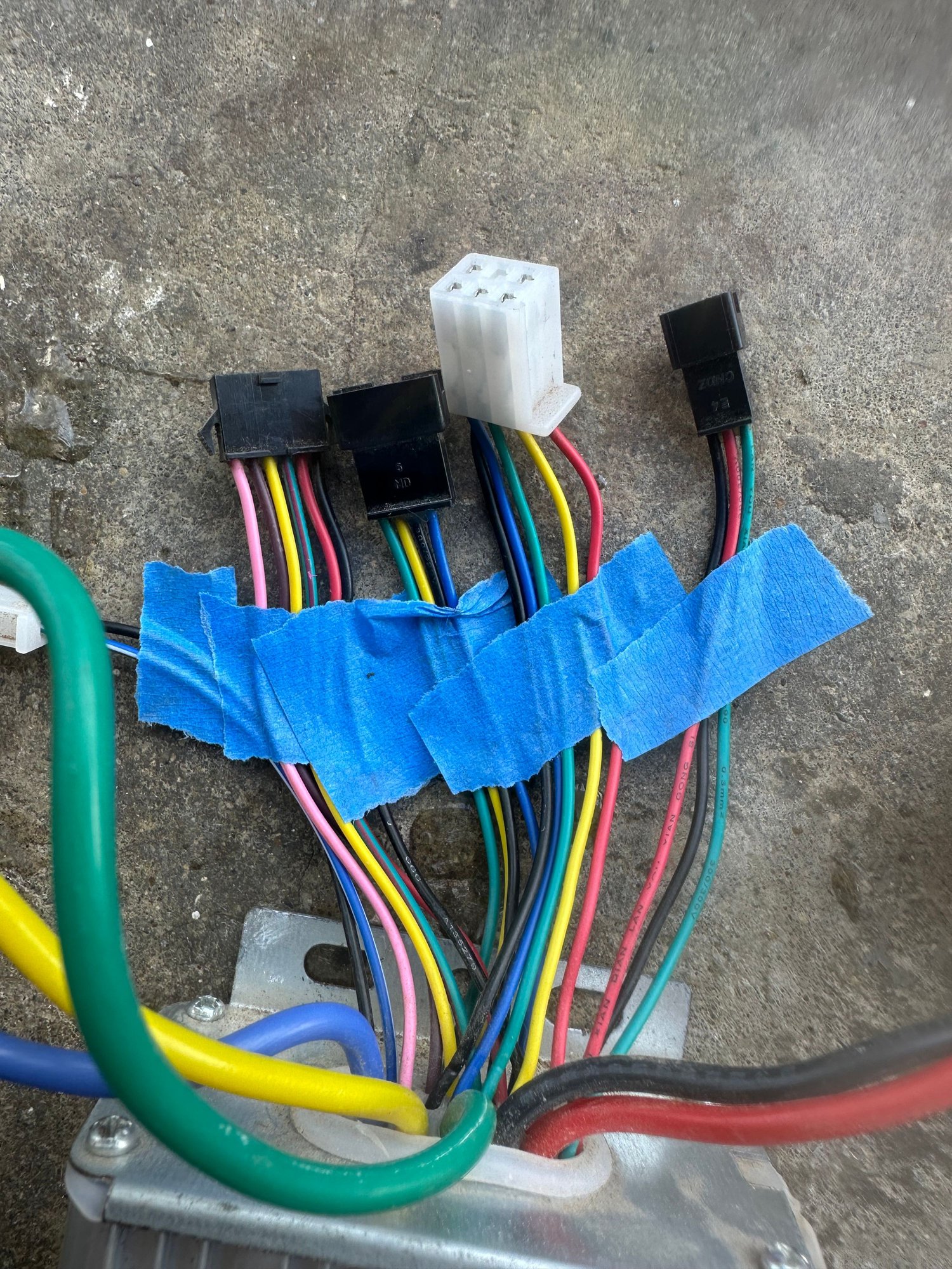
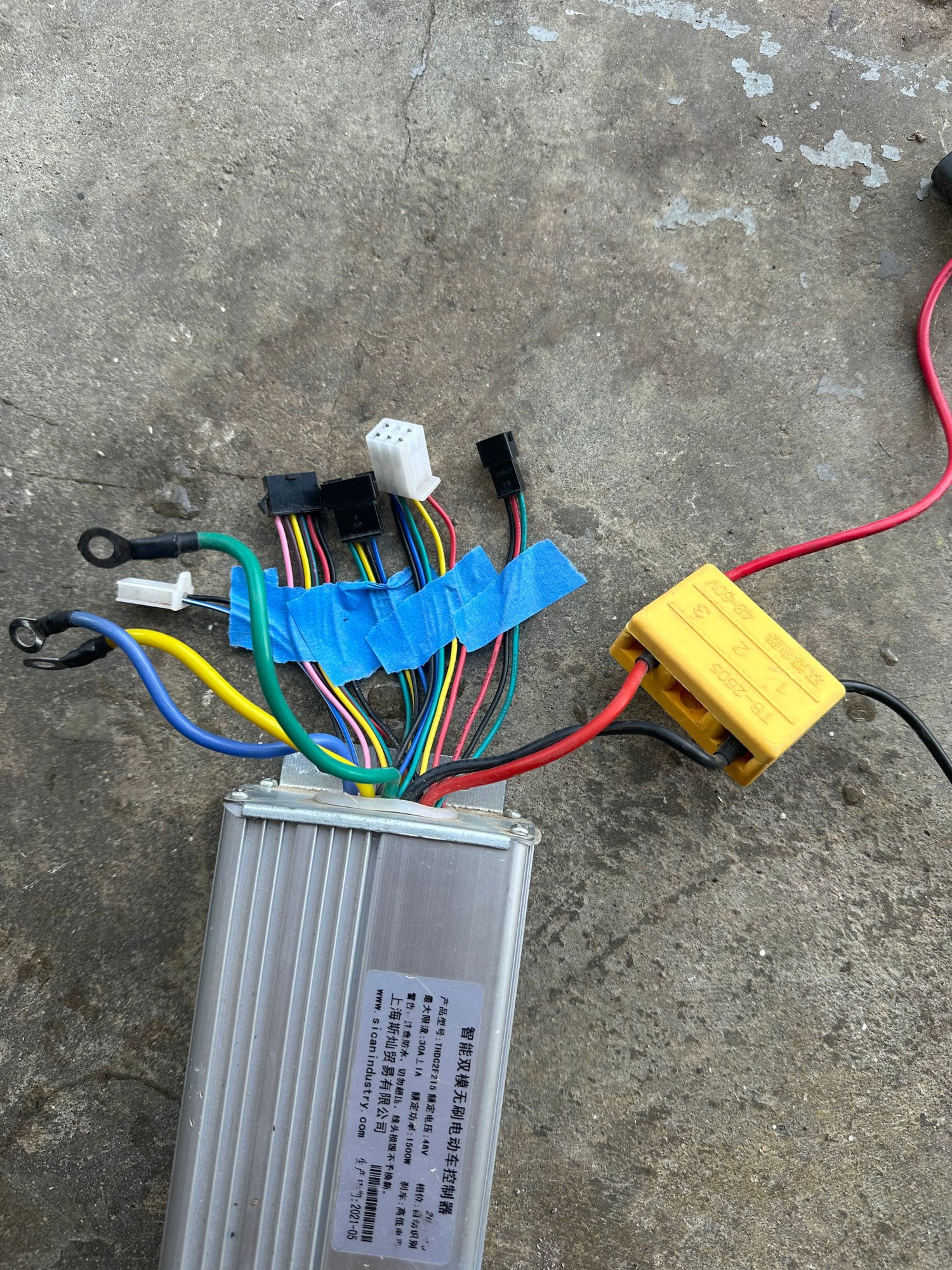
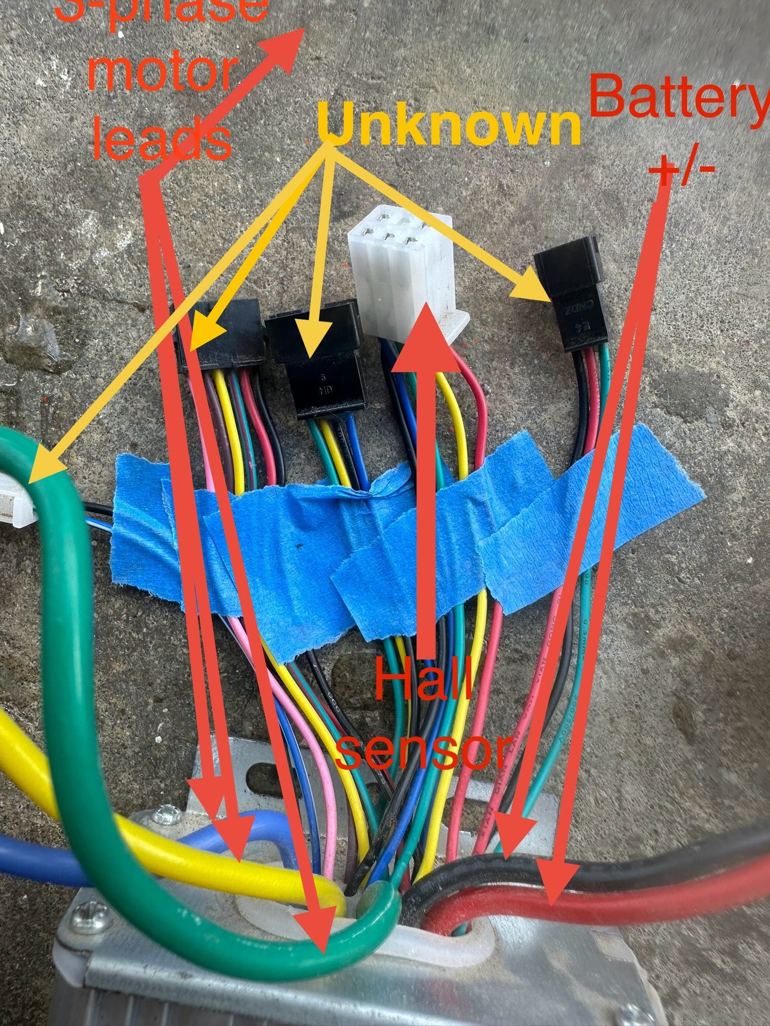
There are five connectors, and five bigger loose wires. I know the bigger wires. Battery +&-, three phases for the motor, but I’m unsure of the connectors.
1. Two wires. Blue/white stripe - black
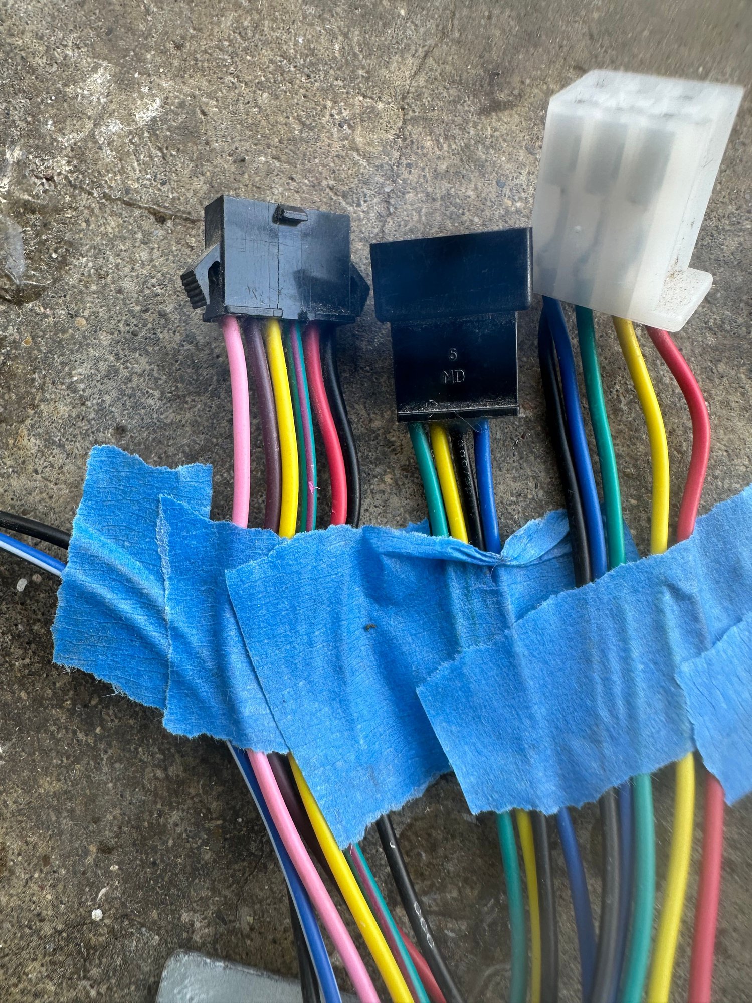
2. Six wires. pink - brown - yellow - green/red stripe - red - black
3. Four wires. green - yellow - black - blue
4. Five wires. black - blue - green - yellow - red
5. Three wires. red - black - green
Thanks so much in advance for helping me solve this puzzle!
There are five connectors, and five bigger loose wires. I know the bigger wires. Battery +&-, three phases for the motor, but I’m unsure of the connectors.
1. Two wires. Blue/white stripe - black
2. Six wires. pink - brown - yellow - green/red stripe - red - black
3. Four wires. green - yellow - black - blue
4. Five wires. black - blue - green - yellow - red
5. Three wires. red - black - green
Thanks so much in advance for helping me solve this puzzle!
 09-25-24 | 11:22 AM
#2


__________________
Carbon: Fuji SL2.1 Di2.......Aluminum: Cannondale Synapse 105........Steel: Vintage Specialized Sirrus
...
Carbon: Fuji SL2.1 Di2.......Aluminum: Cannondale Synapse 105........Steel: Vintage Specialized Sirrus
...
09-25-24 | 12:17 PM
#3
Thread Starter
Newbie
Joined: Sep 2024
Posts: 22
Likes: 1
I don’t know how you did that, but thank you so much! I have four other pictures that will help as well.
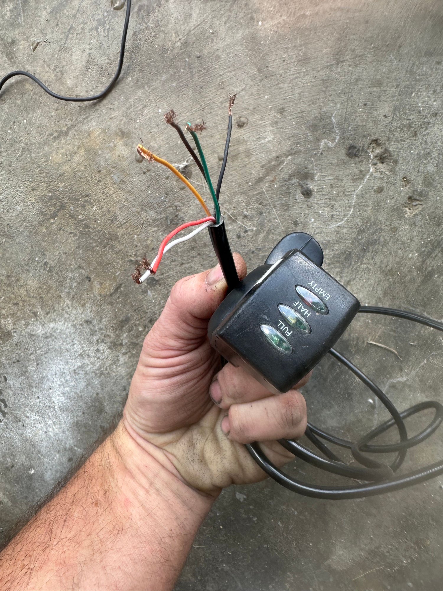
I think I’ve got them all figured out except the five wires coming from the throttle/power switch/voltage meter. The wires are red - black - yellow - green - white - brown
I tried hooking the red white and black wires from the throttle assembly to the red white and black three wire connector.
Thst leaves a yellow, green, and a brown wire.
There is a six wire connector with pink - brown - yellow - green w/red stripe - red - black.
I connected the like colors. Green to green brown to brown and yellow to yellow.
got a spark when I connected the power, but no dice. On off button does nothing. Be nice to get the pictures up.
09-25-24 | 05:51 PM
#5
Senior Member

Joined: Jul 2014
Posts: 5,058
Likes: 1,283
From: socal
Bikes: DIY
The green, yellow and blue are phase wires and correctly connected to their counterparts. You've identified the red & black wires to the battery. The "five" wires look like they connect with the display, two for on/off, two power and a potentiometer for the throttle. There should be eight wires to the motor (six and two?). I'm just trying to help; hopefully DW will answer definitively or go to endless sphere.
09-26-24 | 07:57 AM
#6
Senior Member
Joined: Jul 2015
Posts: 1,589
Likes: 391
From: Chicago Suburbs
Bikes: GT Transeo & a half dozen ebike conversions.
So make ten posts. You can answer these questions, one per post.
1, Is this a commercially purchased ebike or is it a home made job,
2, DO you know if the bike ever ran?
3. How many volts is the system.
4. Does it have a display that shows speed and battery level?
5. Is it throttle only or does it also have pedal assist?
6. Is the motor cable 3 thick wires only or does it also have smaller wires. How many smaller wires, their colors, and type of connector,
7. Do you own a mulitimeter?
8. Izzit true a pic is worth 1000 words?
09-27-24 | 11:32 AM
#7
Thread Starter
Newbie
Joined: Sep 2024
Posts: 22
Likes: 1
So make ten posts. You can answer these questions, one per post.
1, Is this a commercially purchased ebike or is it a home made job,
2, DO you know if the bike ever ran?
3. How many volts is the system.
4. Does it have a display that shows speed and battery level?
5. Is it throttle only or does it also have pedal assist?
6. Is the motor cable 3 thick wires only or does it also have smaller wires. How many smaller wires, their colors, and type of connector,
7. Do you own a mulitimeter?
8. Izzit true a pic is worth 1000 words?
1, Is this a commercially purchased ebike or is it a home made job,
2, DO you know if the bike ever ran?
3. How many volts is the system.
4. Does it have a display that shows speed and battery level?
5. Is it throttle only or does it also have pedal assist?
6. Is the motor cable 3 thick wires only or does it also have smaller wires. How many smaller wires, their colors, and type of connector,
7. Do you own a mulitimeter?
8. Izzit true a pic is worth 1000 words?
it’s a 48V I think 1500W.
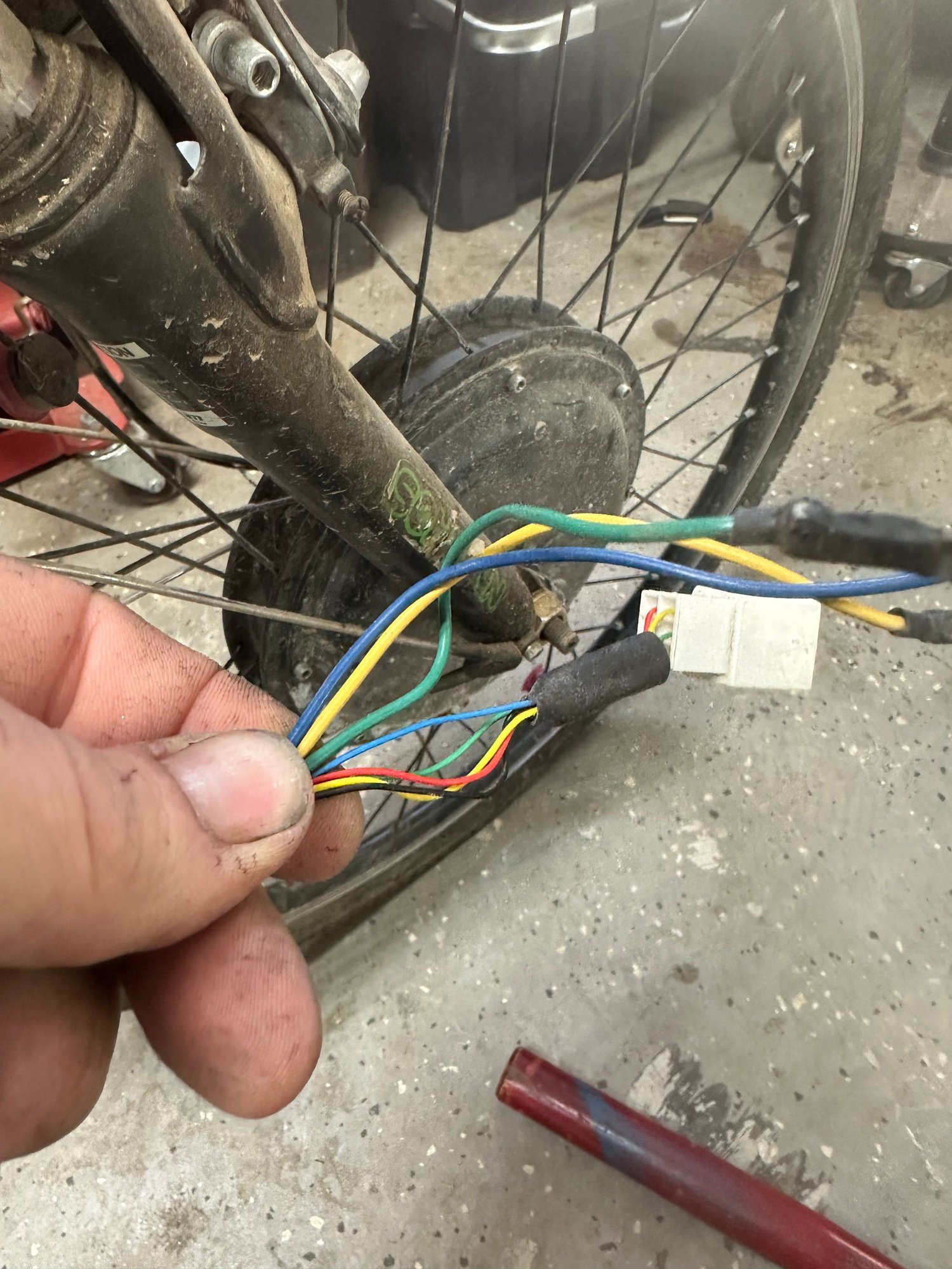
the bike was brought to me with everything on it where it had ran at one time. The controller was in a bag mounted to the frame. The hub motor on the bike and the wiring for it is figured out. What I have left to figure out are the brake lever wires, and the throttle/volt meter/on-off switch assembly.
I think pictures are a 1000 words. It won’t let me post them yet.
thanks for taking the time to reply. Hopefully we can get it figured out.
09-27-24 | 11:40 AM
#8
Thread Starter
Newbie
Joined: Sep 2024
Posts: 22
Likes: 1
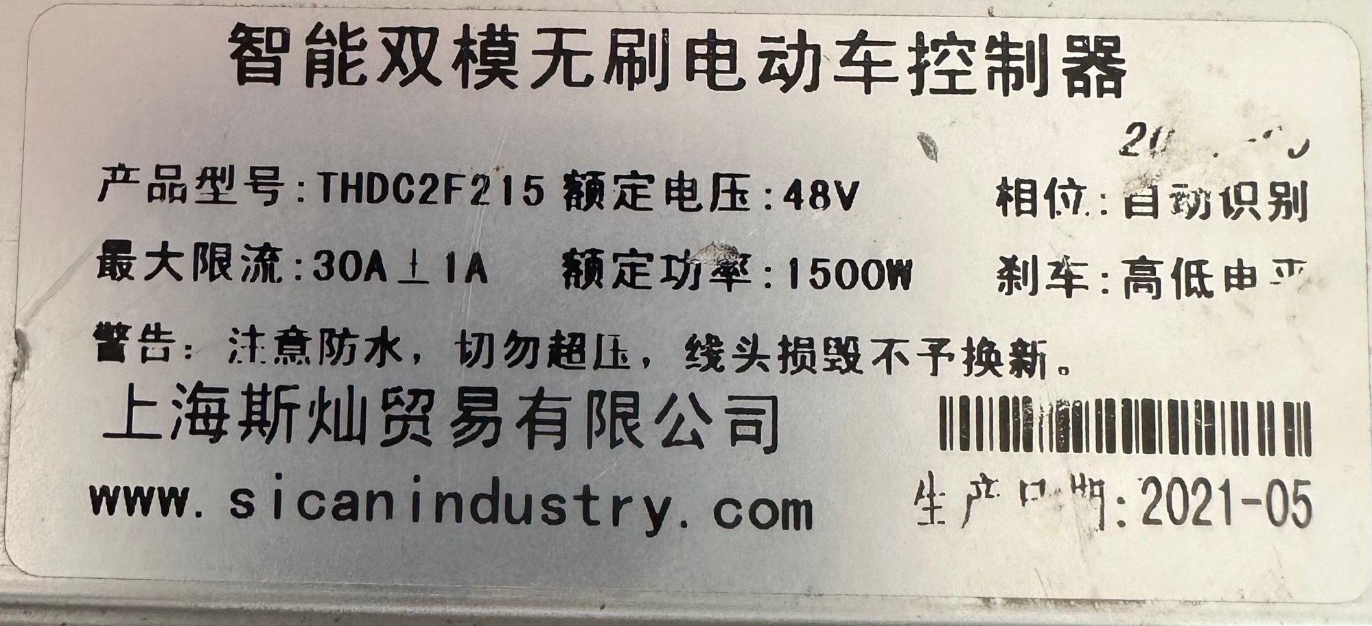
Intelligent dual-mode brushless electric vehicle controller
Product model: THDC2F215 Rated voltage: 48V
Maximum current limit: 1A above 30A
Rated power: 1500W
Warning: Muyi is waterproof, do not overpressure, and damaged threads will not be replaced.
Shanghai Sican Trading Co., Ltd.
20
Phase: self-identification
Brakes: High and low determined by the operator
B 5t p. Hg : 2021-05According to Google, this is the translation of the label
09-27-24 | 03:16 PM
#9
Senior Member
Joined: Jul 2015
Posts: 1,589
Likes: 391
From: Chicago Suburbs
Bikes: GT Transeo & a half dozen ebike conversions.
Are you adding this throttle to replace a simpler one with no key or on/off switch?
Did the bike use a previous display or on/off switch to turn on the bike?
Did the bike use a previous display or on/off switch to turn on the bike?
09-28-24 | 03:22 AM
#10
Thread Starter
Newbie
Joined: Sep 2024
Posts: 22
Likes: 1
I didn’t see any display. It’s got a throttle assembly that has three led’s to show low, mid, and high voltage that acts as a battery level meter. It has a spring catch return on off button the top. So the five wires coming from this assembly need matched to the on/off wires the controller, the throttle, and whatever wires carry battery voltage information.
09-28-24 | 08:31 AM
#11
Senior Member
Joined: Jul 2015
Posts: 1,589
Likes: 391
From: Chicago Suburbs
Bikes: GT Transeo & a half dozen ebike conversions.
It’s got a throttle assembly that has three led’s to show low, mid, and high voltage that acts as a battery level meter.
This is typically how controllers are made.,
The controller has a 48V power connection, a heavy red/black wire pair, but it doesn't turn on until 48V is supplied to a separate input. Your on-off switch should have two wires. One side is 48V and the other side supplies 48V to the controller when it turns on, The 48V side of the switch usually comes from a controller output, but on some bikes they wire it direct to the battery,
A bare throttle has 3 wires. Power (5V), Signal (1.2 to 4 V) and ground, but your unit can indicate battery level? A throttle that can indicate battery level has battery (48V in your case) going to it, Total of four wires with the 4th wire being 48V. The battery leds and the throttle circuits use the same ground, but are independent of each other.
If your throttle also has an on/off switch, now it has 5 wires, the 5th wire carrying battery voltage back to the controller when switched on. Some of these have six wires. but I've never seen one personally,
IF you cannot show a picture of your throttle, at least show where you bought it, Is it something like this one?
https://www.amazon.com/Throttle-Elec...%2C171&sr=8-39
Last edited by Doc_Wui; 09-28-24 at 08:47 AM.
09-28-24 | 01:18 PM
#13
Thread Starter
Newbie
Joined: Sep 2024
Posts: 22
Likes: 1
It still won’t let me. I’ve got to be close to ten posts now….ughhh.
the throttle assembly is kind of like that. It’s only had three separate blights labeled full half and empty.
it has six wires. Red - black - white - yellow - brown- green.
the red wire and black are probably the throttle. It’s a toss up on the other colors.
im more worried about which wires coming from the controller I would connect them to if I know which wires where for what from the throttle. I need to puzzle out the controller first.
 09-28-24 | 02:12 PM
#16
Thread Starter
Newbie
Joined: Sep 2024
Posts: 22
Likes: 1
It’s got a throttle assembly that has three led’s to show low, mid, and high voltage that acts as a battery level meter.
This is typically how controllers are made.,
The controller has a 48V power connection, a heavy red/black wire pair, but it doesn't turn on until 48V is supplied to a separate input. Your on-off switch should have two wires. One side is 48V and the other side supplies 48V to the controller when it turns on, The 48V side of the switch usually comes from a controller output, but on some bikes they wire it direct to the battery,
A bare throttle has 3 wires. Power (5V), Signal (1.2 to 4 V) and ground, but your unit can indicate battery level? A throttle that can indicate battery level has battery (48V in your case) going to it, Total of four wires with the 4th wire being 48V. The battery leds and the throttle circuits use the same ground, but are independent of each other.
If your throttle also has an on/off switch, now it has 5 wires, the 5th wire carrying battery voltage back to the controller when switched on. Some of these have six wires. but I've never seen one personally,
IF you cannot show a picture of your throttle, at least show where you bought it, Is it something like this one?
https://www.amazon.com/Throttle-Elec...%2C171&sr=8-39
This is typically how controllers are made.,
The controller has a 48V power connection, a heavy red/black wire pair, but it doesn't turn on until 48V is supplied to a separate input. Your on-off switch should have two wires. One side is 48V and the other side supplies 48V to the controller when it turns on, The 48V side of the switch usually comes from a controller output, but on some bikes they wire it direct to the battery,
A bare throttle has 3 wires. Power (5V), Signal (1.2 to 4 V) and ground, but your unit can indicate battery level? A throttle that can indicate battery level has battery (48V in your case) going to it, Total of four wires with the 4th wire being 48V. The battery leds and the throttle circuits use the same ground, but are independent of each other.
If your throttle also has an on/off switch, now it has 5 wires, the 5th wire carrying battery voltage back to the controller when switched on. Some of these have six wires. but I've never seen one personally,
IF you cannot show a picture of your throttle, at least show where you bought it, Is it something like this one?
https://www.amazon.com/Throttle-Elec...%2C171&sr=8-39
09-28-24 | 05:22 PM
#17
Senior Member
Joined: Jul 2015
Posts: 1,589
Likes: 391
From: Chicago Suburbs
Bikes: GT Transeo & a half dozen ebike conversions.
Is that picture of the motor in the font fork your pic?
What you're showing appears to be a bare controller not connected to anything, That's a hopeless project without specs on the controller. Sorry, I can't help there. THere's not enough info. I thought you had a bike where you were changing out throttle,
You can buy a 30A controller for 40 bucks with english descriptions of all the connectors. Beats spending hours and hours guessing,
09-29-24 | 12:51 PM
#18
Thread Starter
Newbie
Joined: Sep 2024
Posts: 22
Likes: 1
Yeah that’s what I’m afraid of that without a diagram neither get lucky or ruin the controller.
yesh the motor in the forks is the hub motor.
The hub motor is actually the only thing I’m 100% confident in the wiring for because it hasn’t had its connector snipped off and it matches with the connector on the controller. Like I said I’m needing to figure out what wires on the controller should go to a throttle and any on off switch.
that’s what I need to make it run.
