


Is 28 AWG wire too thin to support 6VAC/3W dynamo power output?
 09-26-12 | 01:51 PM
#1

Thread Starter
Senior Member

Joined: Aug 2008
Posts: 4,134
Likes: 192
From: Somerville, MA and Catskill Mtns
Is 28 AWG wire too thin to support 6VAC/3W dynamo power output?
Electrical engineers, feel free to chime in here!
I'd like to use a short section of two conductor shielded wire (conductor pair + shield) for internally routing through my front rack tubes. I need three conductors total for headlight, taillight and ground (I am not using the fork as ground, even though the dynamo grounds to the fork). There are lots of wire options available, but I'm restricted to using 3mm thick cabling for the internal run, anything fatter won't work. The only two conductor + shield cable I've found that's only 3mm thick uses 28AWG conductors for the pair. It's basically line-level stereo cable. Are these too narrow gauge for this application? Will they heat up? Will there be significant voltage drop? If it matters, the internal run will be no more than 1 foot long. (Voltage drop is proportional to length, right?) All other wiring throughout the system will be 22AWG. the standard for dynamo lighting.
I've bench tested my dynamo lights using about three feet of the 28AWG conductors and they light up fine, but I'm only concerned about potential resistance issues and wires heating up with extended use.
Thanks!
Last edited by southpawboston; 09-26-12 at 01:55 PM.
 09-26-12 | 04:04 PM
#3
Senior Member
Joined: Jul 2006
Posts: 425
Likes: 0
Here is a chart:
https://www.powerstream.com/Wire_Size.htm
There is also a voltage drop calculator on the page.
I'd be more worried about durability. Will there be any flexing? Any wiring from the fork to the frame?
https://www.powerstream.com/Wire_Size.htm
There is also a voltage drop calculator on the page.
I'd be more worried about durability. Will there be any flexing? Any wiring from the fork to the frame?
09-26-12 | 05:43 PM
#4
Certified Bike Brat
Joined: Jan 2011
Posts: 4,251
Likes: 6
From: Montreal, Quebec
Here is a chart:
https://www.powerstream.com/Wire_Size.htm
There is also a voltage drop calculator on the page.
I'd be more worried about durability. Will there be any flexing? Any wiring from the fork to the frame?
https://www.powerstream.com/Wire_Size.htm
There is also a voltage drop calculator on the page.
I'd be more worried about durability. Will there be any flexing? Any wiring from the fork to the frame?
Yup - mechanical durability should be a bigger concern than current carrying capacity. Bicycles produce a lot of vibration and and the wires will slso be exposed to condensation, heat from exposure to the sun etc. Use larger wires.
09-26-12 | 07:29 PM
#5
Thread Starter
Senior Member
Joined: Aug 2008
Posts: 4,134
Likes: 192
From: Somerville, MA and Catskill Mtns
Last edited by southpawboston; 09-26-12 at 07:36 PM.
09-27-12 | 01:40 AM
#6
Senior Member
Joined: Jul 2006
Posts: 425
Likes: 0
I'm not recommending it, but I'm testing army surplus telephone wire for my dynohub setup. 23awg 2 conductor zip line with 4 tinned copper strands and 3 galvanized steel strands per conductor. The insulation is very tough as well, I'm able to split it and run a conductor down the rolled seam of my Honjo fenders. I've also installed it in a Peugeot, replacing the original internal downtube wire. it used the frame as chassis ground, I'm running twin conductor, for an independent ground.
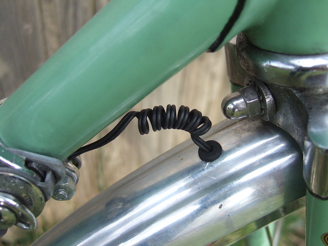
On one bike I've looped it loosely once around the head tube-fork crown area. On the other I've turned the wire around a rod to make a coiled section from the hole in the down tube to the fork mounted light. I think they will both last a long time.
On one bike I've looped it loosely once around the head tube-fork crown area. On the other I've turned the wire around a rod to make a coiled section from the hole in the down tube to the fork mounted light. I think they will both last a long time.
Last edited by krome; 09-27-12 at 01:44 AM.
09-27-12 | 08:00 AM
#7
Thread Starter
Senior Member
Joined: Aug 2008
Posts: 4,134
Likes: 192
From: Somerville, MA and Catskill Mtns

 09-27-12 | 08:15 AM
#8
Thread Starter
Senior Member
Joined: Aug 2008
Posts: 4,134
Likes: 192
From: Somerville, MA and Catskill Mtns
Update: I've tested the light (a re-wired hanging Schmidt Edelux) on my morning commute. I disabled my current dynamo light and plugged in the Edelux with ~3 feet of 28awg wire. I rode about 15 minutes with the light on (short commute). At the end of my commute, the wiring felt as cool to the touch as the unused wiring to my disabled light. I suppose I should test the light more thoroughly, say for an hour or longer with continuous use. But so far it's very promising!
The reason for rewiring the Edelux is because when Schmidt introduced their "hanging" or "inverted mount" Edelux, they disabled the taillight lead because its location would have allowed water penetration. Their solution was to remove the taillight lead altogether. They expect buyers of their $200 light to install a separate taillight switch elsewhere on the bike (inelegant IMHO) or just use a battery taillight. They have the 3mm coax cable that goes from the dynamo to the headlight entering the inverted light through a 3mm drilled hole, sealed with glue from the inside (a crude but effective technique, IMHO). I wanted to keep the look of the svelte 3mm coax cable but needed an extra conductor in there to tap into the taillight circuit (which is still there on the circuit board, just not used). I had wanted to ground the circuit board to the aluminum headlight housing and re-purpose the coaxial braided shield as the main dynamo hot lead, and repurpose the 22awg single conductor for the taillight. But internally grounding the circuit board to the light housing was not possible. My challenge was to find 3mm round cable with three conductors. This limited me to the twin conductor 28AWG with braided shield, sold as line-level audio cable.
I'll post photos of the rewired light soon...
 10-02-12 | 02:45 PM
#10
Senior Member

Joined: Sep 2012
Posts: 1,751
Likes: 7
Seems the size restrictin is for the length of the wire that is going through the hollow of the rack pipe...however the rack is made of metal so it could serve as the shield there, from a shielding standpoint. Thinking you could go up a gauge or two on the wire to gain higher ampacity by just removing the shield where the cable goes through the rack???

Thread
Thread Starter
Forum
Replies
Last Post
bgraham111
Long Distance Competition/Ultracycling, Randonneuring and Endurance Cycling
9
09-11-16 07:35 PM
Pedaleur
Electronics, Lighting, & Gadgets
8
12-26-11 10:18 PM
rhm
Electronics, Lighting, & Gadgets
8
11-04-11 08:46 PM
