


Thread size for pin extraction Dahon V-clamp?
 03-18-25 | 11:22 PM
#1
Thread Starter
Senior Member

Joined: Jan 2017
Posts: 1,245
Likes: 162
Thread size for pin extraction Dahon V-clamp?
Does anyone know the thread size that I need to extract the pin in a hinge of a Dahon V-clamp?
I have a vigor but it should be the same as the Mu.
There is another thread about dismantling the hinge on the Mu in the mechanics forum, but the OP did not know the thread size and someone claimed it was M3.5, however I could not get M3.5x0.6 to engage the threats at all.
The hole itself has a minimum diameter of 2.9 mm so I tried an M3x0.5 and it would only turn two times before it stopped. So either the threat is not 0.5 or it is but the first two threads are damaged.
https://www.bikeforums.net/bicycle-mechanics/1293557-dahon-v-clamp-tear-down.html
 03-19-25 | 02:22 AM
#2
Senior Member

Joined: Aug 2014
Posts: 1,154
Likes: 440
From: UK
Bikes: customized Dahon Helios 1x10, customized Dahon Smooth Hound 1x11, customized Dahon Hammerhead 8.0 d7, Kinesis GX Race 50(mullet setup 1x11), Forme Calver 37 (1x11), Planet X Giovanissimi 20 (1x9), Orange Zest 20 (1x9)
Does anyone know the thread size that I need to extract the pin in a hinge of a Dahon V-clamp?
I have a vigor but it should be the same as the Mu.
There is another thread about dismantling the hinge on the Mu in the mechanics forum, but the OP did not know the thread size and someone claimed it was M3.5, however I could not get M3.5x0.6 to engage the threats at all.
The hole itself has a minimum diameter of 2.9 mm so I tried an M3x0.5 and it would only turn two times before it stopped. So either the threat is not 0.5 or it is but the first two threads are damaged.
Can you access the other side ? and press/push it out with a tamp?
03-19-25 | 03:00 AM
#3
Thread Starter
Senior Member
Joined: Jan 2017
Posts: 1,245
Likes: 162
No, there's no access from the top.
I went to the local bike store and they strongly threaded in an M3 bolt, but could not extract the pin by pulling on it. They tried 40 minutes. They think it's corroded or bent into the cam cylinder since wiggling the bolt when it's in the pin will turn the lever back and forth. They tried WD40 on it too.
I'm thinking of tapping it with M3 and pulling on the tap itself, but I'm worried about getting the tap stuck inside and then I won't be able to insert the safety set screw that's supposed to prevent the pin from falling out.
The plan was to open it up to see why the play in the hinge has developed and whether replacing the pin would help any. I also thought about wrapping the pivot pins (the large pins that are fixed to the frame) with adhesive aluminum foil 0.05-0.1mm thick would reduce the play. But I think the foil would probably rip apart.
Maybe I should leave it as it is.
03-19-25 | 03:17 AM
#4
Senior Member
Joined: Aug 2014
Posts: 1,154
Likes: 440
From: UK
Bikes: customized Dahon Helios 1x10, customized Dahon Smooth Hound 1x11, customized Dahon Hammerhead 8.0 d7, Kinesis GX Race 50(mullet setup 1x11), Forme Calver 37 (1x11), Planet X Giovanissimi 20 (1x9), Orange Zest 20 (1x9)
No, there's no access from the top.
I went to the local bike store and they strongly threaded in an M3 bolt, but could not extract the pin by pulling on it. They tried 40 minutes. They think it's corroded or bent into the cam cylinder since wiggling the bolt when it's in the pin will turn the lever back and forth. They tried WD40 on it too.
.
03-19-25 | 03:28 AM
#5
Senior Member
Joined: Aug 2014
Posts: 1,154
Likes: 440
From: UK
Bikes: customized Dahon Helios 1x10, customized Dahon Smooth Hound 1x11, customized Dahon Hammerhead 8.0 d7, Kinesis GX Race 50(mullet setup 1x11), Forme Calver 37 (1x11), Planet X Giovanissimi 20 (1x9), Orange Zest 20 (1x9)
The plan was to open it up to see why the play in the hinge has developed and whether replacing the pin would help any. I also thought about wrapping the pivot pins (the large pins that are fixed to the frame) with adhesive aluminum foil 0.05-0.1mm thick would reduce the play. But I think the foil would probably rip apart.
.
.

Brake Pad Anti Squeal Backing Pads 3M
03-19-25 | 05:21 AM
#6
Junior Member
Joined: Apr 2011
Posts: 146
Likes: 80
From: Vancouver BC
Bikes: 2000 Raleigh M20, 2010 Dahon Eco3, 1995 Gary Fisher Montare, 2024 SoloRock Dash
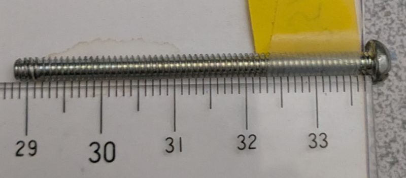
Here's a picture of the screw that worked for me. I don't know where it came from - was in my miscellaneous screws box. It measures 3.46mm across the threads, and has a Roberts #1 socket.
Inch rule:
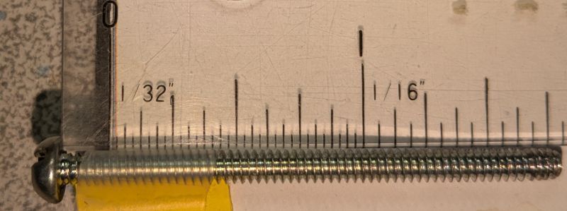
1/32" pitch, it would seem. Edit: after further checking - that screw is actually a #6 - 32.
Inch rule:
1/32" pitch, it would seem. Edit: after further checking - that screw is actually a #6 - 32.
Last edited by Antifriction; 03-19-25 at 07:14 PM.
03-19-25 | 07:11 AM
#7
Thread Starter
Senior Member
Joined: Jan 2017
Posts: 1,245
Likes: 162
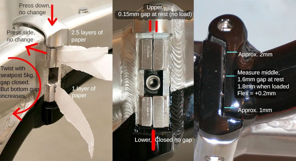
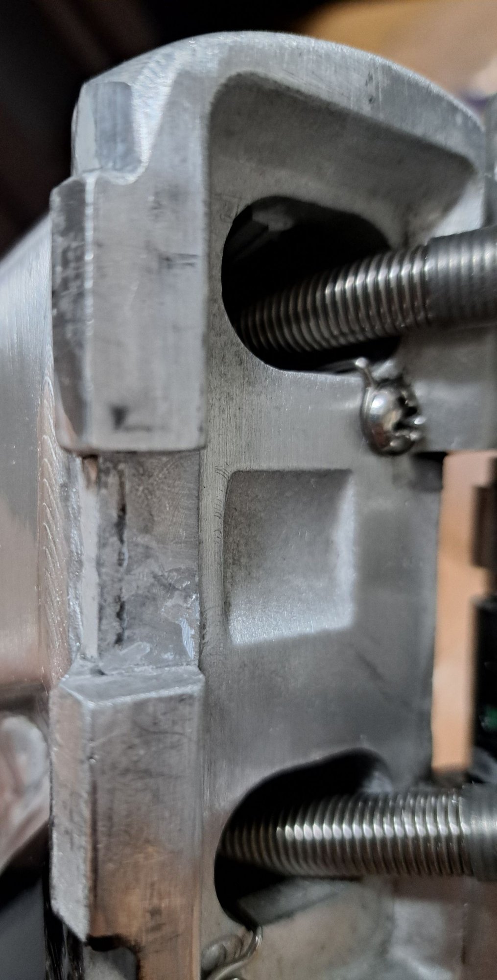
I remember now. Back in 2018 when I first bought the bike, I noticed that the two teeth on the two halves of the hinge plates do not actually contact when the frame is closed. Instead the center slot is the only point of contact with the 13 mm block. So when the latch is tightened then there's about a 0.5 mm gap between the two teeth allowing the hinge to rotate and flex. What I did was I filed down the inside faces of the teeth to make them as parallel as possible and then shimmed them so that they almost touched when the latch was closed. This greatly reduced the flex.
Last year just before I started the tour in Japan, one of the shims fell out and was lost, so I removed the other one too. it was during the middle of the ride that the problem occurred with the hinge starting to develop play. So I guess for the 6 years before that, the shims prevented this from happening.
I had forgotten the importance of why I put the shims in there, otherwise I would have immediately replaced the one that I lost.
I'll try measuring the gap again to shim the gap between the teeth, and then maybe on the pin edge I will add some aluminum tape to try spacing out the runout that has developed.
03-21-25 | 09:41 PM
#8
Thread Starter
Senior Member
Joined: Jan 2017
Posts: 1,245
Likes: 162
I've ordered a #6 screw and will test it when I get it.
I noticed that the 13 mm block has worn down a groove into the hinge plates. I assume this happened slowly but probably accelerated after I lost the shims.
I'm not sure if the groove had worn flat or convex from the rocking. I'll try sanding it down since it may prevent the latch from closing fully. I'll also try to chamfer the edge of the block.
I'll shim the tips of the tabs again but still leave about 0.05-0.1 mm gap since it would be dangerous if the 13mm block wasn't touching the hinge plates and the shims fall out again.
Such a bad design. Wish I had replaced the lost shim earlier, then the hinge would have been just like new.
03-24-25 | 12:01 PM
#9
Thread Starter
Senior Member
Joined: Jan 2017
Posts: 1,245
Likes: 162
I got a #6 bolt but unable to confirm whether it's the correct thread because the M3 threads have been forced into the pin hole. The pin is stuck to the cam cylinder and cannot be removed without cutting off the latch. I assume the repetitive opening closing of the latch and the bending of the frame has caused the pin to fuse or corrode between dissimilar materials, or it's bent. So I'll just leave the pin alone.
The purpose of the pin isn't to hold the hinge together but to transfer the torque from the lever and the cam cylinder to the clamp.
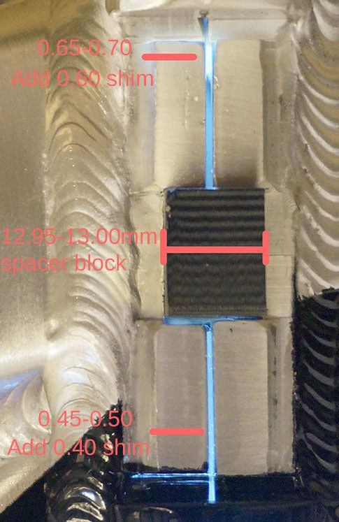
I've added the lost shims back to the two halves of the hinge plates. Instead of the old 0.6 and 0.4, I used 0.5 and 0.3mm. I've also added some shims to the pivot pin side to to try padding out any play.
I reduced the thickness of the shims because the repetitive opening closing of the latch, have worn down the aluminum surface by around 0.2 mm. This would theoretically cause the front and rear wheels to misalign by 10mm.
So now there is a total of 0.1 mm gap between the aluminum surface and the 13 mm block on the clamp. The two surfaces are not parallel anymore by around 0.1mm, probably due to the rocking wearing down the aluminum material when the old shims were removed, which I guess is how the original design was supposed to perform.
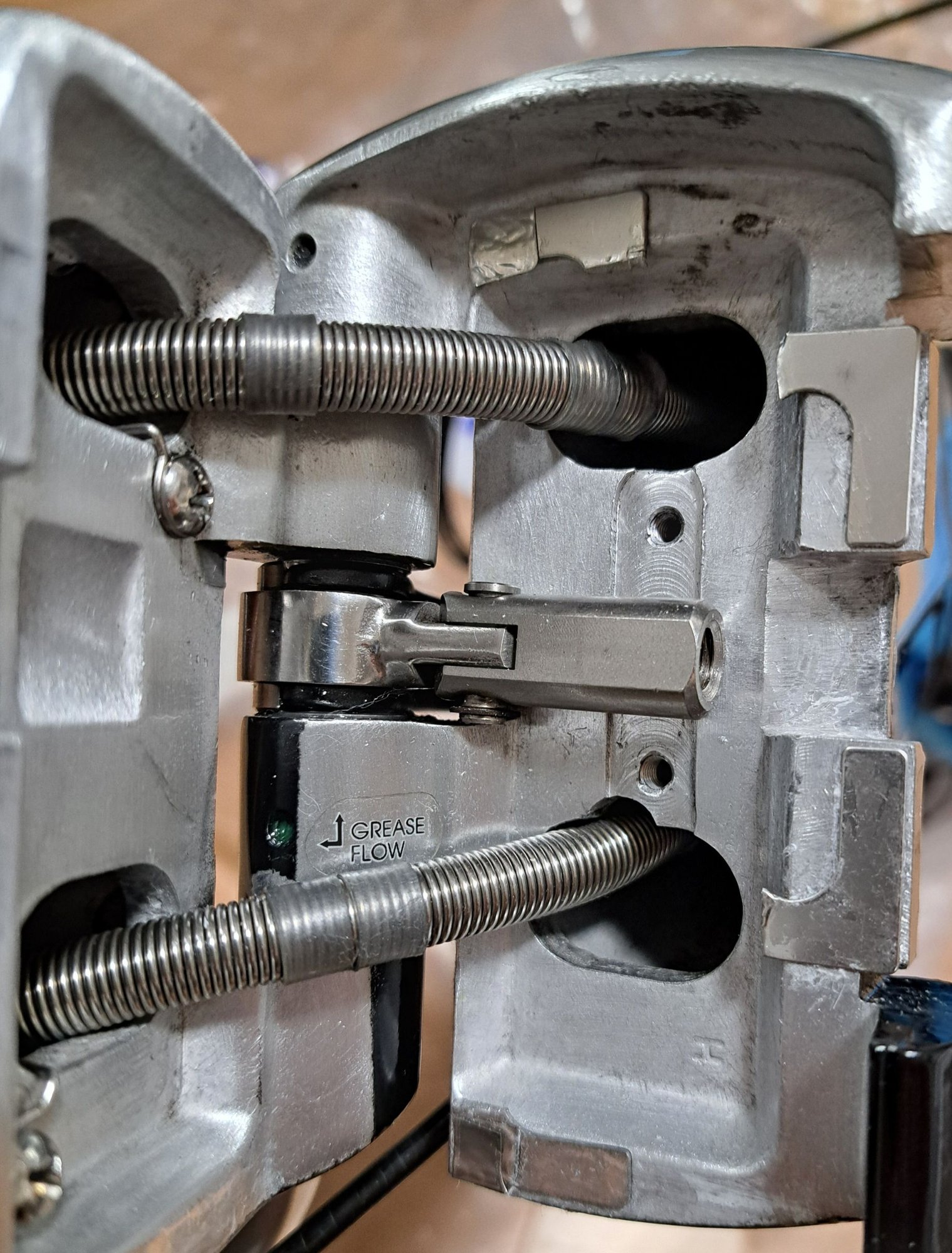
I also sanded down the divots or ridges that was formed by the repetitive opening and closing of the latch.
The old shims were made of bronze but the new ones are stainless steel. However I've used shims that are made up of stacked layers of 0.5 mm sheets that you peel off to reduce the thickness. That's probably weaker than a single homogenous sheet so I'm not sure if it would deform or thin out over time.
The purpose of the pin isn't to hold the hinge together but to transfer the torque from the lever and the cam cylinder to the clamp.
I've added the lost shims back to the two halves of the hinge plates. Instead of the old 0.6 and 0.4, I used 0.5 and 0.3mm. I've also added some shims to the pivot pin side to to try padding out any play.
I reduced the thickness of the shims because the repetitive opening closing of the latch, have worn down the aluminum surface by around 0.2 mm. This would theoretically cause the front and rear wheels to misalign by 10mm.
So now there is a total of 0.1 mm gap between the aluminum surface and the 13 mm block on the clamp. The two surfaces are not parallel anymore by around 0.1mm, probably due to the rocking wearing down the aluminum material when the old shims were removed, which I guess is how the original design was supposed to perform.
I also sanded down the divots or ridges that was formed by the repetitive opening and closing of the latch.
The old shims were made of bronze but the new ones are stainless steel. However I've used shims that are made up of stacked layers of 0.5 mm sheets that you peel off to reduce the thickness. That's probably weaker than a single homogenous sheet so I'm not sure if it would deform or thin out over time.
Last edited by tomtomtom123; 03-24-25 at 09:59 PM.
03-24-25 | 09:06 PM
#10
Highly Enriched Driftium


Joined: Apr 2017
Posts: 6,715
Likes: 2,174
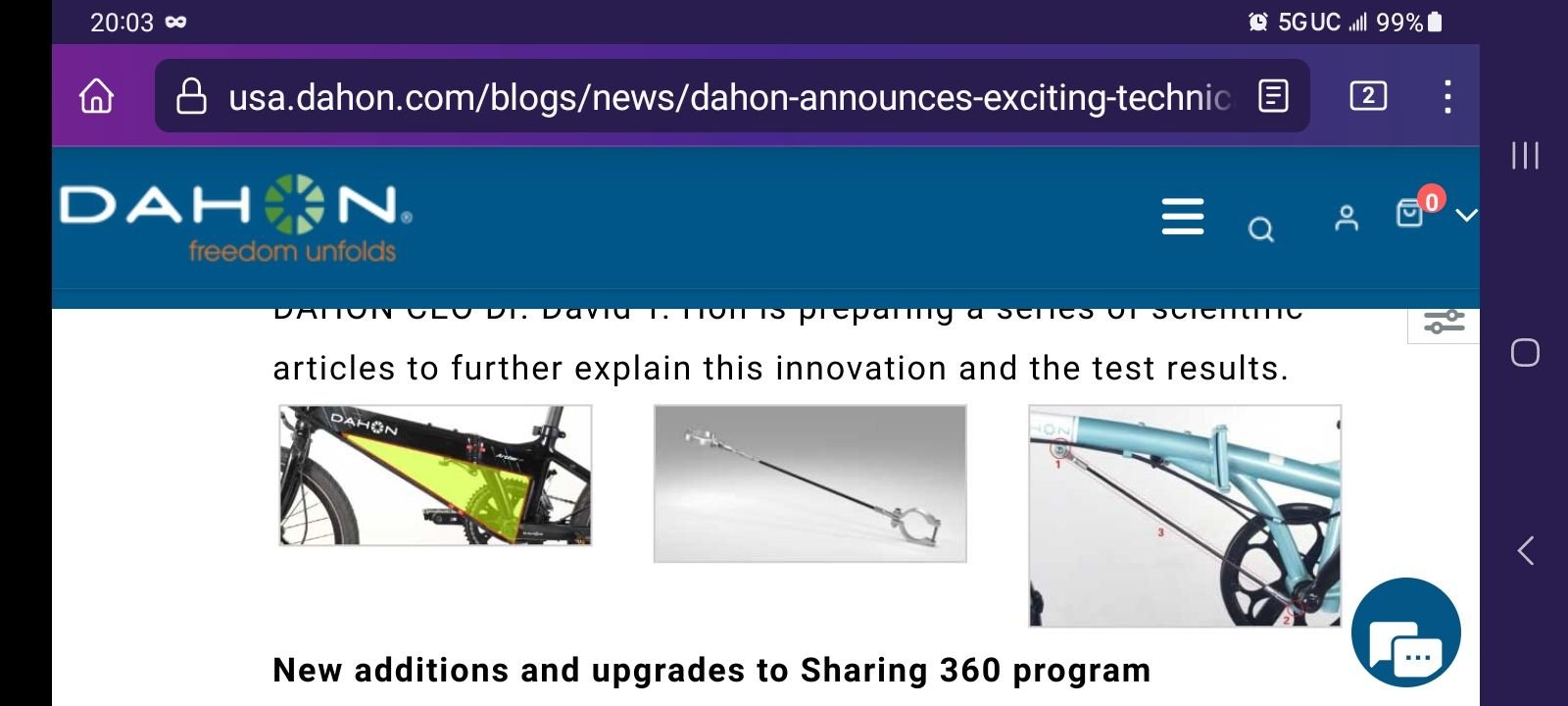
OP: If you put a deltech cable (loaded in tension) on it, you'll eliminate the bending load on that hinge joint and place the frame tube and hinge into compression shear on the pin, eliminating a lot of the wobble. Torsion loads into the frame beam, like when climbing standing, will not be affected, but the hinge will be tighter. Any cable must be low-stretch; Steel (like Dahon's), kevlar, or UHMWPE like Spectra, Dyneema, etc. The line must be very taut when unfolded. Photo below is from before I secured the line ends. Knot must not slip, I used 8 bend with kevlar line which I happened to have some, kevlar is slippery so requires a good knot:

03-25-25 | 02:50 AM
#11
Senior Member
Joined: Aug 2014
Posts: 1,154
Likes: 440
From: UK
Bikes: customized Dahon Helios 1x10, customized Dahon Smooth Hound 1x11, customized Dahon Hammerhead 8.0 d7, Kinesis GX Race 50(mullet setup 1x11), Forme Calver 37 (1x11), Planet X Giovanissimi 20 (1x9), Orange Zest 20 (1x9)
The old shims were made of bronze but the new ones are stainless steel. However I've used shims that are made up of stacked layers of 0.5 mm sheets that you peel off to reduce the thickness. That's probably weaker than a single homogenous sheet so I'm not sure if it would deform or thin out over time.
08-22-25 | 04:37 AM
#13
Thread Starter
Senior Member
Joined: Jan 2017
Posts: 1,245
Likes: 162
I'm revisiting this problem again since the shim that I glued on has fallen off so I'm replacing them. The play hasn't increased much since my last post which was around 2,000 to 3,000 km ago of loaded touring. But I did compare it with a brand new Mu hinge which is similar to the Vigor/vector hinge. The brand new Mu has no play.
On my frame, unlatch the hinge, it appears as if the boreholes have ovalized, allowing the main pin to wiggle around. The amount of movement is very small maybe around 0.2 mm. I still can't get the retaining pin to come out, as it's probably gouged into the cam or slightly bent so I cannot disassemble to check. I thought about cutting through the retaining pin to extract it but there is a risk that it's stuck even after cutting, leaving an unusable frame so I have not done it.
But I thought I saw the main pin rotating freely in the borehole where it's supposed to be a press fit, when looking through the hole at the bottom. Possibly the press fit borehole has ovalized and is no longer holding the pin.

I'm just wondering at what point would it be unsafe to use? Chat AI keep on telling me it's extremely dangerous like I'm going to die or something.
Does anyone know if the upper main pin has the hole where the retaining pin goes into, whether that hole passes through all the way to the other end? I want to know if I tried to cut through the retaining pin whether I can tap it out from the top if there's a hole there. If not, I won't try because of the risk of it getting stuck inside the hole.

And even if I could remove the retaining pin, is there any point, since there's no way to repair an ovalized borehole? Does anyone know if this main pin is actually pressed fit or perhaps threaded? If it's just threaded in, perhaps I can simply tighten it, But I think that's unlikely.
On my frame, unlatch the hinge, it appears as if the boreholes have ovalized, allowing the main pin to wiggle around. The amount of movement is very small maybe around 0.2 mm. I still can't get the retaining pin to come out, as it's probably gouged into the cam or slightly bent so I cannot disassemble to check. I thought about cutting through the retaining pin to extract it but there is a risk that it's stuck even after cutting, leaving an unusable frame so I have not done it.
But I thought I saw the main pin rotating freely in the borehole where it's supposed to be a press fit, when looking through the hole at the bottom. Possibly the press fit borehole has ovalized and is no longer holding the pin.
I'm just wondering at what point would it be unsafe to use? Chat AI keep on telling me it's extremely dangerous like I'm going to die or something.
Does anyone know if the upper main pin has the hole where the retaining pin goes into, whether that hole passes through all the way to the other end? I want to know if I tried to cut through the retaining pin whether I can tap it out from the top if there's a hole there. If not, I won't try because of the risk of it getting stuck inside the hole.
And even if I could remove the retaining pin, is there any point, since there's no way to repair an ovalized borehole? Does anyone know if this main pin is actually pressed fit or perhaps threaded? If it's just threaded in, perhaps I can simply tighten it, But I think that's unlikely.
Last edited by tomtomtom123; 08-22-25 at 04:42 AM.
08-22-25 | 01:06 PM
#14
Thread Starter
Senior Member
Joined: Jan 2017
Posts: 1,245
Likes: 162
OP: If you put a deltech cable (loaded in tension) on it, you'll eliminate the bending load on that hinge joint and place the frame tube and hinge into compression shear on the pin, eliminating a lot of the wobble. Torsion loads into the frame beam, like when climbing standing, will not be affected, but the hinge will be tighter. Any cable must be low-stretch; Steel (like Dahon's), kevlar, or UHMWPE like Spectra, Dyneema, etc. The line must be very taut when unfolded. Photo below is from before I secured the line ends. Knot must not slip, I used 8 bend with kevlar line which I happened to have some, kevlar is slippery so requires a good knot:
M4, M5, or M6?

Edit: the Kevlar or dynema ropes are braided so won't they lengthen when the frame bends? What about a stainless steel cable? 2mm or 3mm? Cable and u bolt clamp only $3. Maybe need shrink wrap to protect the frame from gouging.
Last edited by tomtomtom123; 08-22-25 at 03:26 PM.
08-22-25 | 11:10 PM
#15
Highly Enriched Driftium
Joined: Apr 2017
Posts: 6,715
Likes: 2,174
Meanwhile I'll search for a Kevlar rope, but how do you keep the tension while tying the 8 bend knot, because don't you have to pull the ends to tighten it, causing slack? What about a $2 turnbuckle with a locking nut?
M4, M5, or M6?
Edit: the Kevlar or dynema ropes are braided so won't they lengthen when the frame bends? What about a stainless steel cable? 2mm or 3mm? Cable and u bolt clamp only $3. Maybe need shrink wrap to protect the frame from gouging.
M4, M5, or M6?
Edit: the Kevlar or dynema ropes are braided so won't they lengthen when the frame bends? What about a stainless steel cable? 2mm or 3mm? Cable and u bolt clamp only $3. Maybe need shrink wrap to protect the frame from gouging.
Well, I happened to have a piece of kevlar line laying around, just long enough for the loop you see. How did I get it tight? I tied it with the bike slightly folded, gently started to unfold it to check tension, nope, not quite tight enough, shortened it, just enough so that I had just a bit of difficulty fully unfolding the frame, so laid it flat and gently used my foot to snap it to fully unfolded, tension was perfect, and has not loosened the tiniest bit, nor stretch, in 3+ years now. (You need to be careful with the above, because once that 8 bend is really tight, it'll be a bear to get undone. Needs to get the length right before that knot goes tight.) But an adjustable setup would be easier. I could also do same loop but add some small loops to do a single or double or triple trucker's hitch; These days, many round-the-world sailboats are replacing stainless steel cable standing rigging with swaged fittings (which can't be repaired as sea, unless you brought replacements with you), for high strength line (usually one of the brands of UHMWPE these days) with multiple "blocks" (pulleys) in 2/3/4:1 or more for enough leverage to tension up the sailing rigs, no turnbuckles, simpler, and fatigues less than stainless cable and end fittings. Lighter (I think 1/7 the weight of steel for same strength), very durable, nearly zero stretch, no creep over time, no corrosion, UV resistant, and easy to replace at sea, just standardize and have a spool of that line on board, cut to length. UHMWPE is also UV resistant, whereas Kevlar is not, it's actually off-white and the line you see on mine is actually painted black on the outside by the maker for UV protection. But Kevlar is almost completely supplanted in the market by UHMWPE, which also comes in multiple groovy colors.
With the ovalized holes as you mentioned... deltech cable will force the hinge closed tightly, and loading the pin in shear instead of bending couple, but if the holes are large, I don't know if, with the hinge closed tightly, it will be tight on the pin top and bottom, or not. I did my deltech soon enough that the hinge is drum-tight when unfolded. Noticeable difference; Gone is clunk-clunk slack with front brake on and rocking bike back and forth, and frame is a lot stiffer at the hinge when climbing standing, which puts the hinge in torsion.
Last edited by Duragrouch; 08-22-25 at 11:24 PM.
08-23-25 | 01:47 AM
#16
Thread Starter
Senior Member
Joined: Jan 2017
Posts: 1,245
Likes: 162
Is there any risk of cracking the head tube from the concentrated loading from the cable wrapped around it?
Should I use a single loop or two loops?
A single loop is one continuous cable with the ends connected by the turnbuckle by the cable end looped back onto itself to form an eyelet, so there are two strands running from the head tube to the bottom bracket. Two separate loops means that there's one closed loop around the head tube and another closed loop around the bottom bracket and they're joined together by the turnbuckle. The two separate loops are joined by their own ends aligned in parallel so there are no eyelets or bends.
Single-loop:
Load: Turnbuckle sees half the total system tension.
Angles: Sharper bends at cotter pin and clamp → slightly more slack.
Pros: Safer for turnbuckle, lower stress.
Cons: Slightly more slack, sharper angles.
Two separate loops:
Load: Turnbuckle sees full system tension.
Angles: Gentler, straighter into clamps → less slack.
Pros: Less slack, easier clamp grip.
Cons: Higher stress on turnbuckle and pin
And should I use a thimble in the loop at the ends of the cable? It has a curvature to it And also the diameter of the eyelet of the thimble is twice the diameter of the pin at the end of the turnbuckle which is a cylinder so the thimble contacts the pin at a single point. I'm wondering if the thimble will deform and act as a spring causing slack whenever the frame is loaded which would reduce its ability to remove the play in the hinge. If I don't use a thimble, the bend in the bare cable where it forms the eyelet around the turnbuckle pin will gradually flatten or deform or fray But it will be permanent and won't spring back so there won't be slack.
Last edited by tomtomtom123; 08-23-25 at 09:34 AM.
08-24-25 | 03:33 AM
#17
Highly Enriched Driftium
Joined: Apr 2017
Posts: 6,715
Likes: 2,174
Is there any risk of cracking the head tube from the concentrated loading from the cable wrapped around it?
Should I use a single loop or two loops?
A single loop is one continuous cable with the ends connected by the turnbuckle by the cable end looped back onto itself to form an eyelet, so there are two strands running from the head tube to the bottom bracket. Two separate loops means that there's one closed loop around the head tube and another closed loop around the bottom bracket and they're joined together by the turnbuckle. The two separate loops are joined by their own ends aligned in parallel so there are no eyelets or bends.
Single-loop:
Load: Turnbuckle sees half the total system tension.
Angles: Sharper bends at cotter pin and clamp → slightly more slack.
Pros: Safer for turnbuckle, lower stress.
Cons: Slightly more slack, sharper angles.
Two separate loops:
Load: Turnbuckle sees full system tension.
Angles: Gentler, straighter into clamps → less slack.
Pros: Less slack, easier clamp grip.
Cons: Higher stress on turnbuckle and pin
And should I use a thimble in the loop at the ends of the cable? It has a curvature to it And also the diameter of the eyelet of the thimble is twice the diameter of the pin at the end of the turnbuckle which is a cylinder so the thimble contacts the pin at a single point. I'm wondering if the thimble will deform and act as a spring causing slack whenever the frame is loaded which would reduce its ability to remove the play in the hinge. If I don't use a thimble, the bend in the bare cable where it forms the eyelet around the turnbuckle pin will gradually flatten or deform or fray But it will be permanent and won't spring back so there won't be slack.
Should I use a single loop or two loops?
A single loop is one continuous cable with the ends connected by the turnbuckle by the cable end looped back onto itself to form an eyelet, so there are two strands running from the head tube to the bottom bracket. Two separate loops means that there's one closed loop around the head tube and another closed loop around the bottom bracket and they're joined together by the turnbuckle. The two separate loops are joined by their own ends aligned in parallel so there are no eyelets or bends.
Single-loop:
Load: Turnbuckle sees half the total system tension.
Angles: Sharper bends at cotter pin and clamp → slightly more slack.
Pros: Safer for turnbuckle, lower stress.
Cons: Slightly more slack, sharper angles.
Two separate loops:
Load: Turnbuckle sees full system tension.
Angles: Gentler, straighter into clamps → less slack.
Pros: Less slack, easier clamp grip.
Cons: Higher stress on turnbuckle and pin
And should I use a thimble in the loop at the ends of the cable? It has a curvature to it And also the diameter of the eyelet of the thimble is twice the diameter of the pin at the end of the turnbuckle which is a cylinder so the thimble contacts the pin at a single point. I'm wondering if the thimble will deform and act as a spring causing slack whenever the frame is loaded which would reduce its ability to remove the play in the hinge. If I don't use a thimble, the bend in the bare cable where it forms the eyelet around the turnbuckle pin will gradually flatten or deform or fray But it will be permanent and won't spring back so there won't be slack.
If using steel cable, it should be a "single" straight cable like Dahon does, no wrap around the head tube or bottom bracket shell.
If using soft high-strength/stiffness line like I did, I like the single loop like mine, as you said, the turnbuckle sees half the tension due to double strands, but more importantly, there should only be half the stretch (strain) in the line, and you want maximum rigidity; Too much stretch, and you get bending loads into the hinge instead of just pure compression shear.
I think the stresses due to line wrap around the head tube and bottom bracket, are small. You have a large line area due to large radius. I have zero concerns on my steel frame. Aluminum... perhaps a bit more, but still less concerns than the small tabs Dahon welds on for Deltech; I had seen Deltech disappear from aluminum frames but not steel, and theorized they might be having fatigue problems on the welded aluminum tabs (too short in front, and loaded in bending at the BB), and then I saw the following for the Japan market, eliminating the forward welded tab, which may confirm my suspicions:

The "Add-On" Deltech (top middle pic in my post #10 above) which Dahon talked about but seems to be vaporware, has steel ring clamps which go around the head tube and bottom bracket, so there; I think low-stretch line would put less stress there than thin steel clamps.
Thimbles: Those are critical for steel cable, which requires a minimum bend radius; Without them, a loop in the steel cable would have a ton of spring to it so not stiff enough, and rapidly fatigue and strands crack. (With steel cable, a better strategy is a single straight cable with swaged end fittings, like the Dahon Deltech.) With very flexible high strength line, it is much more tolerant. Tiny thimbles at the turnbuckle attachments might be good, but I think instead just show careful attention to:
- holes that line are attached to are well chamfered, no sharp edge or shape,
- careful choice of knots and exactly how they are tied; line stress can vary greatly by knot type, some reducing line rated strength significantly. I chose an 8-bend, but even there, it's important that the tension ends (versus free ends) are correct, often taking the route of larger radius instead of smaller, where the line is against another layer in the knot; look online for instructions. And also, use a knot that holds well with slippery line; The downside is that those knots are often very hard to undo, so get it right the first time. Another possible option might be a double-bowline, tied just like a standard bowline, but two loops at the beginning of the process, it holds twice the tension, but I think easier to untie than a tight 8-bend. For application where the loop may take a lot of wear, I like a bowline-on-a-bight, because it's a bowline that ends up with two layers of attachment loop instead of one, I'll often use that as the loop part of a trucker's hitch, because it takes abrasion of the line rubbing hard against it, when cinching down.
Oh yes, if using a straight steel cable with swaged end fittings, you don't have welded tabs on the frame like Dahon, so yes, just closed loops around the head tube and bottom bracket to attach to, will be fine. If the holes on your swage fittings are large enough, the closed loops can be double, two wraps and one knot, if two thicknesses of line will go through the holes on the swage fittings. If not, don't worry about it; The skinny line you see on my bike? That'll lift my car. Strong stuff. But I would say, the V extending from the loop(s) to attach to, have the included angle there be no more than about 70 degrees (35 degrees each side); too big an angle there will increase the line tension in the loop a lot. A longer V (smaller included angle) reduces the tension.
Last edited by Duragrouch; 08-24-25 at 04:07 AM.
09-19-25 | 05:31 AM
#18
Thread Starter
Senior Member
Joined: Jan 2017
Posts: 1,245
Likes: 162
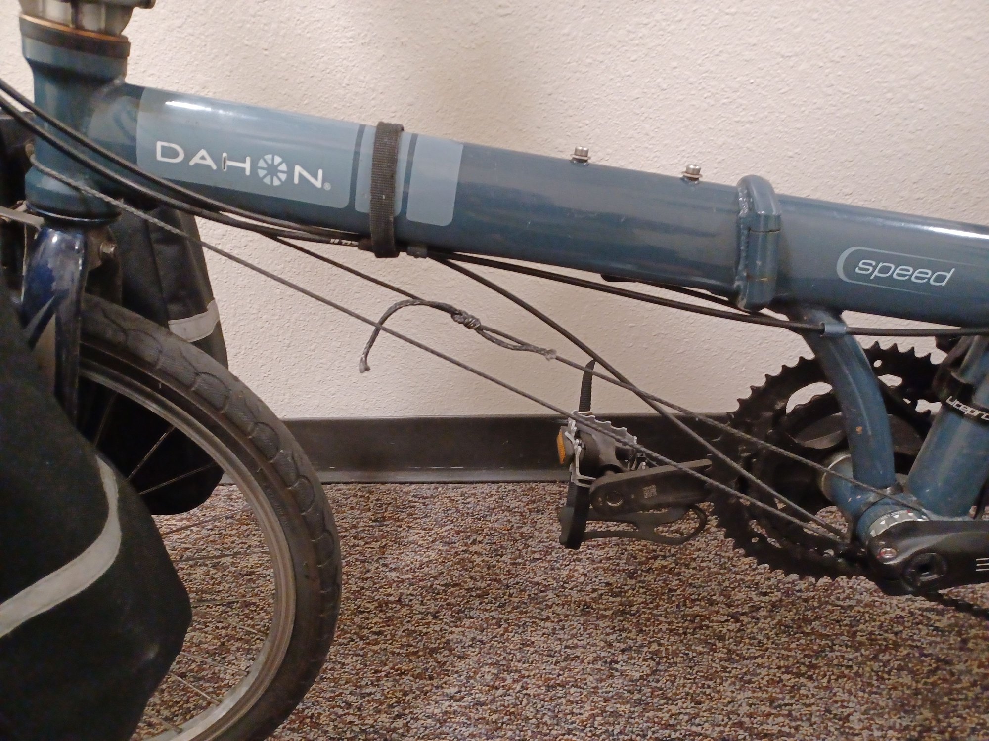
I used a 5 mm Dynema rope. The steel cable was too stiff and really hard to work with. I wrapped the rope on both sides of the bottom bracket and a single loop around the head tube.
There is almost zero play in the hinge now. However because there are two strands in parallel on both sides of the bottom bracket, when folding the bike the rope has to lengthen initially. Because of this each time I'm unfolding the rope loses some tension because I think the figure eight knot is settling.
So I have to tension the turnbuckle but I only got two centimeters left before I need to redo the knot to reduce the length of the rope.


I've also wrapped tape around the two strands near the bottom bracket and the head tube to keep the rope from slipping off from the slack when folded. The photos are from before I added the tape.
There is almost zero play in the hinge now. However because there are two strands in parallel on both sides of the bottom bracket, when folding the bike the rope has to lengthen initially. Because of this each time I'm unfolding the rope loses some tension because I think the figure eight knot is settling.
So I have to tension the turnbuckle but I only got two centimeters left before I need to redo the knot to reduce the length of the rope.
I've also wrapped tape around the two strands near the bottom bracket and the head tube to keep the rope from slipping off from the slack when folded. The photos are from before I added the tape.
09-19-25 | 09:36 PM
#19
Highly Enriched Driftium
Joined: Apr 2017
Posts: 6,715
Likes: 2,174
I used a 5 mm Dynema rope. The steel cable was too stiff and really hard to work with. I wrapped the rope on both sides of the bottom bracket and a single loop around the head tube.
There is almost zero play in the hinge now. However because there are two strands in parallel on both sides of the bottom bracket, when folding the bike the rope has to lengthen initially.
There is almost zero play in the hinge now. However because there are two strands in parallel on both sides of the bottom bracket, when folding the bike the rope has to lengthen initially.
My loop is around bottom and top of non-drive (left) side of BB shell only. It has to go just a bit "over center" when unfolding but not bad at all. Having line on the drive side, yeah, that will be a lot harder to fold, and, it might be very close to your inner chainring. However, left side only like mine, the line can fall off over the left crank arm when folded, you'd need to watch that.
"Zero play in the hinge now"; People think I'm hyping or scamming them on this. It really works; "Lighter than air, stronger than steel, cheaper than dirt.
EDIT: Your bike, I'm liking what I'm seeing! Hollow crank with external bearings, 2X crank (looks like originally a 3X, with chainguard on the outside and 74mm BCD inner for great low gear). I don't see any front derailleur, I loved adding that to mine, especially if I occasionally drop a chain (if chainline is at cross-extremes when I front shift), shift to the other ring and the chain instantly pops back on. FD adapter was hard enough for my Speed frame, but on your style frame it may be more difficult, it's 1mm larger clamp diameter and the FD bracket attachment is further back:
Style on mine:

Style to fit yours:

Last edited by Duragrouch; 09-19-25 at 10:02 PM.
10-01-25 | 07:46 AM
#20
Thread Starter
Senior Member
Joined: Jan 2017
Posts: 1,245
Likes: 162
I bought wingnuts so that I could loosen and tighten the turnbuckle by hand but I forgot that one of the nuts is left-handed. So I just glued nuts to it.
One problem I have is that whenever I fold and then unfold I have to force the cable back onto the BB shell because when folding the slack causes the cable to slip onto the BB cup on the non-drive side.
So it's probably better if I move the turnbuckle to the non drive side so that whenever I loosen it to fold I get more slack to work.
10-02-25 | 03:13 AM
#21
Highly Enriched Driftium
Joined: Apr 2017
Posts: 6,715
Likes: 2,174
I bought wingnuts so that I could loosen and tighten the turnbuckle by hand but I forgot that one of the nuts is left-handed. So I just glued nuts to it.
One problem I have is that whenever I fold and then unfold I have to force the cable back onto the BB shell because when folding the slack causes the cable to slip onto the BB cup on the non-drive side.
So it's probably better if I move the turnbuckle to the non drive side so that whenever I loosen it to fold I get more slack to work.
My line is pretty tight (non-adjustable), and with it looped *only* around the left (non-drive) side of the bottom bracket shell, it does not need loosening to easily fold the bike, because then the line is in nearly the same plane as the hinge pin. Dahon's Deltech also attaches same, the welded tab at the bottom bracket for the cable is offset toward the non-drive side. There is no need to loosen their Deltech setup to fold. It's that line on yours to the drive side, offset from the hinge pin to the side that needs to expand initially to fold, that is making your fold difficult, or requiring you to loosen the turnbuckle.
